Losses in Armoured Three Core Power Cables
Losses in three-core armoured power cables have historically been calculated using the formulas presented in the IEC Standard 60287-1-1. The formulas are based on semi empirical research on cables with smaller conductor cross sections and common sheath which is not representative of the design trend of today’s cables. For armoured three-core cables with greater insulation thickness and larger conductor cross sections than those used in the past, the accuracy of IEC 60287-1-1 is insufficient as the standard typically overestimates the cable losses resulting in over dimensioning of the cables and increased cost.
Members
Convenor
(NO)
R. STØLAN
Secretary
(SE)
D. PALMGREN
K. ABKEN (GE), G. ANDERS (CA), D. CHATZIPETROS (GR), L. COLLA (IT), Y. DOUIMA (FR), M. HATLO (NO), H. HEO (KR), U. HUANG (UK), W. KAMARA (1ST QUARTER) (CA), J. PILGRIM (UK), S. STURM (GE), R. SVOMA (UK), O. THYRVIN (SE), K. YONEYA (JP), K. ZHANG (CN), J. ZHANG (NL)
Corresponding Members
B. BRIJS (BE), A. GODARD (FR)
Introduction
International commitments to reduce greenhouse gasses alongside with government funding has led to a step change in the competitiveness of the renewable energy market in recent years. Wind and solar power are the renewable technologies with the largest growth rates and are expected to generate roughly 70 % of the world’s energy needs by 2050, while coal powered electricity plants are expected to drop to 10 %.
Replacing offshore gas powered generators with renewable power from shore and fossil fuelled generation onshore with power from offshore wind are just two examples of the measures to reduce carbon emissions where power cables play an important role and constitute a significant part of the total project cost.
Efforts to improve the financial viability of offshore wind puts pressure on windfarm developers and cable manufacturers to reduce the cost of both export and array cables.
Increased wind turbine size and installed power, more specialised installation vessels, project synergies, experience and optimised supply chain are some factors that contributed to a cost reduction of 18 % of installed offshore wind between 2010 and 2019. In addition to upscaling the wind farms, another trend is moving them further away from the shore.
Interconnecting transmission cables increase redundancy by enabling energy flow between countries depending on the generation and demand. As the number of offshore wind farms increases, the use of combined export- and interconnecting cables may provide another level of redundancy.
With AC-transmission reaching distances of more than 200 km, having accurate cable parameters is essential for finding the correct system design and calculating capital and operational expenditures. Using accurate cable parameters for the cable design results in potentially large cost savings when compared to designs calculated using IEC 60287-1-1.
Scope and Contents of the Technical Brochure
The members of Study Committee B1 voted in the 2017 SC meeting in New Delhi, to establish a Working Group (WG) to study the topics of the scope proposed by Task Force B1.64. As part of this scope, WG-B1.64 has developed analytical formulae which is verified by measurements of cables using the group’s standardised loss measurement procedure and 3D Finite Element Analysis (FEA). A method for measuring of the magnetic permeability of armour wires is proposed and utilized by the WG to obtain values for the armour wires of the measured cables in order to compare the results from the loss measurements with the loss calculations.
The Technical Brochure is divided into the following chapters:
Chapter 1 “Introduction” contains the introduction, background, terms of reference and a guide for the contents of the TB to help the reader navigate the different subjects.
Chapter 2 “Cable losses overview” describes the physics responsible for the losses in the cable. It explains how the different parts of the cable interact with each other with the aid of illustrations from Finite Element Analysis. The background of the formulas of IEC 60287-1-1 are discussed and compared in a qualitative way to the current understanding of the physics behind the losses in three-core armoured cables.
Chapter 3 “Calculations” introduces two analytical calculation methods. Results obtained using methods 1 and 2 are compared extensively throughout the TB. Method 1 has been in continuous development by the WG. Method 2 is used as originally published [7].
Chapter 4 “Impedance measurements” addresses important factors related to the measurement of the cable impedance and recommends minimum requirements for the equipment to obtain accurate measurement results. Impedance measurements of three-core armoured power cables have been conducted by members of the working group prior to and during the course of the WG activities. The results from these measurements play a central role in the development of these recommendations, as they contribute to the verification of the results from the 3D Finite Element Analysis and the analytical formulas.
Chapter 5 “Magnetic permeability measurements” presents the method used by the working group to obtain values of the permeability from several armour wire samples, including samples from cables on which impedance measurements have been performed. The results from the permeability measurements are compared and discussed.
The magnetic permeability of the armour wires is an important parameter when calculating the losses in the cable. Hysteresis losses result in a cable resistance that is non-linear with the applied current.
Mechanical stress in the armour wires influences the magnetic permeability. This is not a focus for this TB, but the topic is briefly discussed, and the effect highlighted based on test results.
Chapter 6 “Finite Element Analysis” gives a detailed account of the different subjects related to the 3D Finite Element Analysis for three-core armoured power cables presented in this TB. The sensitivity of mesh size and the geometrical properties are discussed to provide recommendations for modelling using 3D FEM (Finite Element Method).
Chapter 7 “Discussion” presents a brief study with calculations of the thermal rating for three cables with different parameters with the calculated losses from method 1 and the IEC method. The chapter illustrates the benefits of performing accurate cable calculations by comparing the resulting cable designs calculated with method 1 and the IEC method and discussing the different possibilities for cable design optimisation.
The process of verifying the different calculation methods with impedance measurements is explained and the results from the process are presented and compared.
Results from the FEA of a double layer flat wire armoured cable are compared with the measurements. The purpose of this discussion is to suggest a method of calculating the parameters of flat wire and/or double layer armoured cables as none of the methods presented in this TB have this capability.
Topics that have seen new development during the course of this work, but which have not been included in this TB due to time constraints are discussed, along with potential future improvements.
Appendix A “References” presents the literature that is directly referenced in this TB.
Appendix B “Abbreviations and symbols” lists abbreviations and symbols used in this TB.
Appendix C “Application of equations method 1” provides a numerical calculation example of method 1 with specified input to help guide the reader through the steps of the calculations in order to aid the understanding and arrive at the same answer.
Appendix D “Application of impedance measurement procedure” presents an example of an actual measurement performed by the working group members on one of the cables used as an example throughout the TB. It complies with the general requirements and procedure of chapter 5 and is the method utilised for almost all the measurements described in this TB.
Appendix E “Comparison of results” compares all the results from the cases calculated using FEA, methods 1 and 2 and IEC 602871-1. For each cable, the common cable parameters for a set of cases are given in a separate table to make comparison between the cases easier.
After checking that the fundamental properties of the methods capture all the mechanisms of the physics responsible for the cable losses, the range of cables for which the methods have been evaluated by measurements, is extended. This allowed a comparison of the results obtained with the analytical formulas and FEA for cables with a wider range of parameters than of those that were measured.
Appendix F “Cable data” presents data for the cables that are measured and for which a comparison with FEM and analytical methods has been made.
Conclusion
The physics responsible for the losses in a cable are presented, gradually increasing in complexity, starting with a single conductor and finishing with a complete three-core cable with stranded armour. The effect of sea water conductivity on the cable losses is verified to have an insignificant impact based on both analytical consideration and Finite Element Analysis (FEA). The background of the formulas of IEC 60287-1-1 is discussed and compared in a qualitative way to the current understanding of the physics behind the losses in three-core armoured cables.
Two calculation methods, “method 1” and “method 2”, are presented in the TB. Method 1 is an analytical method developed by the WG members, while method 2 is a numerical method referenced and used in the TB as published prior to the WG. The main difference between them is that method 1 considers the conductor proximity effect on the magnetic field, while method 2 formulas do not include the conductors. These differences are reflected in the results – method 1 more accurately accounts for losses induced in sheaths and armour for most cases, while method 2 is slightly overestimating the sheath and armour losses. Both methods handle magnetic and non-magnetic armour.
The calculation methods are verified by loss measurements. Figure 1 compares the measured cable losses from six different cable designs with the values obtained by different calculation methods. The calculated losses from the methods are in good agreement with the measured losses, except for IEC 60287, which significantly overestimates the losses in the cables with magnetic armour.
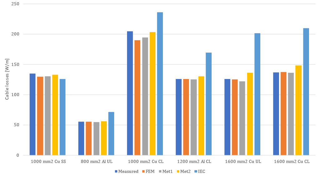
Figure 1 - Comparison of measured and calculated total cable losses. The UL and CL suffix specifies unilay and contralay armour respectively. SS specifies stainless steel (non-magnetic) armour
The WG has performed measurements on several cables and the recommended procedure is presented with an example following all the steps used during the actual measurement of one of the cables in the TB. Important factors, from test object preparation and the correct use of equipment, to post processing of data and error estimation are discussed.
3D Finite Element Analysis (FEA) is used extensively in the comparison of more than one hundred cases. The developed model is used to aid in the understanding of cable losses and for verifications of physical phenomena during the development of method 1. 3D FEA is the recommended method for cables with double layer or flat wire armour since none of the other calculation methods includes these options. This is one of the identified areas for further work.
2D FE models are not able to capture the 3D nature of the mechanisms responsible for the losses in the cable. Table 1 compares the losses calculated using 2.5D and 3D for four different cable designs. For unilay cables (with long crossing pitch) the agreement is good. For contralay cables the 2.5D method underestimates the losses. The underestimation increases with decreasing conductor resistance and increasing permeability of the armour, while for smaller conductors carrying less current and armour with low permeability, the accuracy of the 2.5D method improves.
| Conductor | 1600 mm2 Cu | 1200 mm2 Al | 1600 mm2 Cu | 1000 mm2 Cu |
|---|---|---|---|---|
Armour lay | Unilay | Contralay | Contralay | Contralay |
Permeability | 150-j50 | 150-j50 | 150-j50 | 600-j350 |
Difference [%] | -2.8 % | -9.2 % | -12.6 % | -20.3 % |
The magnetic permeability of armour wires is an important parameter for the accurate calculation of cable losses. It influences not only the losses in the armour wires, but also the losses in conductors and screens. The non-linear properties of the armour result in a current dependant resistance. Results from magnetic permeability measurements of several samples, including samples from the measured cables, are presented and discussed in the TB. Mechanical stress in the armour wires influences the magnetic permeability. This is not a focus for this TB, but the topic is briefly discussed, and the results from a test performed by the WG show the effect.
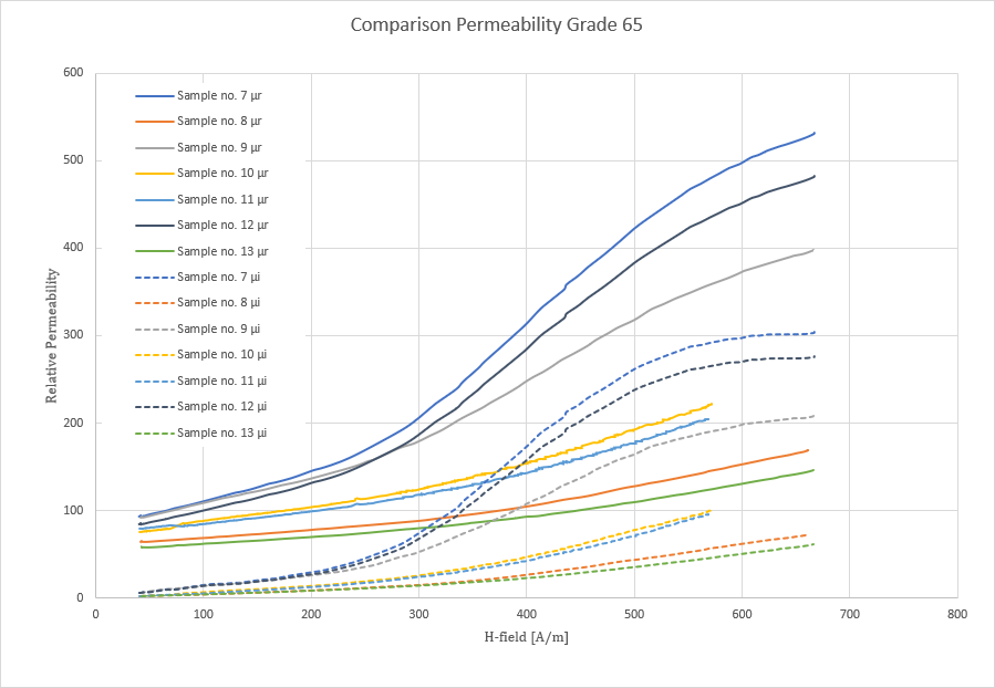
Figure 2 - The real (continuous line) and the imaginary (dashed line) part of the magnetic permeability for 7 different grade 65 armour wire samples
Calculations of the thermal rating for three cables with different armour designs with the calculated losses from method 1 and IEC 60287-1-1 are performed. Table 1 shows the maximum ampacity for a 1200 mm2 aluminium cable with different armour configurations calculated with method 1. In the same table, the conductor cross section required to achieve the same ampacity according to IEC 60287-1-1 is shown. A significant reduction of the conductor cross section is possible for all the cable designs when calculating the losses with method 1.
| Calculation method | Grade 34 Contralay (950 A) | Grade 65 Contralay (990 A) | Grade 34 Unilay (1025 A) |
|---|---|---|---|
Method 1 | 1200 mm2 | 1200 mm2 | 1200 mm2 |
IEC 60287-1-1 | 1600 mm2 | 1800 mm2 | 2000 mm2 |
For a cable with copper conductors, Table 3, the difference becomes even greater due to the increased skin effect in the conductors. The reduction of conductor cross section of 600 mm2 as seen for the first cable, would impact the cost of the cable with approximately 27 % for the materials alone. The potential cost savings may become even greater when considering the cost of manufacturing and the impact of the 19 % (2277 tonnes for a cable with a length of 100 km) reduction in weight on the number of required installation campaigns.
Calculation method | Grade 34 Contralay | Grade 65 Contralay | Grade 34 Unilay |
|---|---|---|---|
Method 1 | 1200 mm2 | 1200 mm2 | 1200 mm2 |
IEC 60287-1-1 | 1800 mm2 | > 2000 mm2 | |

Other Technical Brochures