Mobile substations incorporating HV GIS
CIGRE Working Group B3.41 was tasked with an investigation and assessment of mobile, prefabricated and build-off-site substations for the following scope:
• Drivers for deployment of mobile substations
• Benefits of using mobile substations.
• Experience of implementation and operation, including relevant case studies
• Applicability of existing standards
• Guidelines for specification and design
Members
Convenor
(UK)
P. FLETCHER
Secretary
(DE)
S. CRAY
F. DISSON (FR), F. GEBHARDT (DE), A. GOYVAERTS (BE), P. GROSSMANN (US), J. LOPEZ-ROLDAN (AU), D. MAGANTO (ES), C. MARTIN (BE), V. MURPHY (IE), N. OTAKA (JP)
Scope of Working Group
In recent years several utilities have reported on the use of ‘mobile’ substations employing a high level of off-site construction. A number of specific objectives have been described, such as the ability to quickly substitute a failed transformer in an emergency; however, the underlying aim is the ability to provide new, extended or replacement substation facilities either at short notice and/or with a reduced site construction period compared with traditional solutions. There is a growing interest in such ‘build off-site’ solutions as transmission and distribution owners come under pressure to respond rapidly to changing user demands. The ability to respond to these demands is one element in delivering smarter grids for the 21st Century.
Mobile substations generally, although not exclusively, utilise GIS technology with many designs based on compact switchgear assemblies with the addition of integrated protection and control facilities. Thus, in addition to individual standards covering the design and testing of the functional components of the substation, the following existing standards are partly relevant to mobile substations:
- IEC62271 High-voltage switchgear and controlgear - Part 202: High voltage/low voltage prefabricated substation
- IEC62271 High-voltage switchgear and controlgear - Part 205: Compact switchgear assemblies for rated voltages above 52 kV
These standards, however, do not necessarily consider the specific requirements for design, construction and testing of mobile substations and it was identified that recommendations were required on this issue.
In some circumstances, depending on the application, it may not be appropriate for mobile substations to fully comply with conventional standards regarding, for example, foundations, environmental conditions or testing requirements. The work of CIGRE WG B3.41 aims to give recommendations on how to consider these topics.
The early adopters of mobile substation technology have now gained valuable experience regarding the design, testing, implementation and use of mobile substations and CIGRE Study Committee B3 decided that it would be valuable to capture this experience. WG B3.41 was established to undertake this task and the resulting Technical Brochure presents the conclusions of the work.
The main focus of the Technical Brochure is on the incorporation of GIS technology into mobile substations. The WG does not aim to give guidance on specific design and testing requirements for other types of equipment such as transformers or Protection & Control (P&C).
Structure and content of the Technical Brochure
The scope and main results of this Technical Brochure includes the contents below.
- INTRODUCTION ON MOBILE SUBSTATIONS:
- What is a mobile substation?
- Types of mobile substations
- Development of technologies to enable wider use of mobile substations
- Drivers and benefits of mobile substations
- GUIDELINES FOR SPECIFICATION AND DESIGN OF MOBILE SUBSTATIONS
- Transport/road regulations
- Mechanical requirements
- Design requirements specific to location
- Deployment
- TESTING OF MOBILE SUBSTATIONS
- Introduction to testing
- Variation in test requirements between standards and mobile substations
- Recommendations for testing of mobile substations
- Summary of test requirements
- ASSET MANAGEMENT
- Storage
- Maintenance
- Asset life
- Gas handling and gas management
- General considerations for redeployment
- EXPERIENCE OF MOBILE SUBSTATIONS
- Summary of case studies
- In-service experience
- RECOMMENDATIONS FOR THE APPLICABILITY OF EXISTING STANDARDS
- CONCLUSION
- APPENDIX: CASE STUDIES
Chapter 1 presents the concept of mobile substations and the motivation to design a mobile substation instead of a conventional substation. The WG established 3 categories of mobile substations:
- Type A mobile substation: “short term emergency type unit” typically used for:
- Unplanned deployment to replace failed equipment, bays or the complete substation
- Planned deployment to support maintenance works or to provide short time network enhancement.
- Type B mobile substation: “intermediate type unit” typically used for:
- Unplanned deployment to replace failed equipment, bays or substations (longer deployment time than emergency type)
- Planned deployment to support infrastructure works or to provide network enhancement for a longer period of time.
- Type C mobile substations: “semi-stationary type unit” typically used for:
- Planned deployment as an alternative to a conventional substation where resources (e.g. skilled labour) are not readily available or costs are high
- Planned deployment as an alternative to a conventional substation when site works are difficult or impossible (eg offshore substation).
Figure 1 shows an example of the three types of mobile substations.
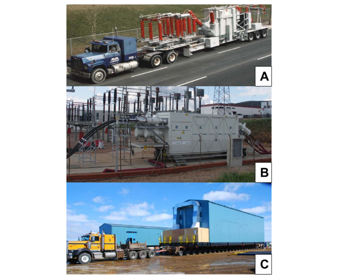
Figure 1 - Examples of mobile substations type A, B and C
The drivers for selecting each type of mobile substation are summarised in table 1
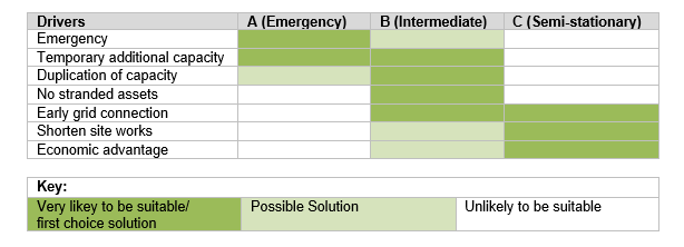
Table 1 - Overview of Drivers in relation to Types of Mobile Substation
Chapter 2 presents some guidelines for the specification and design of mobile substations emphasizing the specific conditions not considered in conventional substations such as the requirement for relocation, the road regulations, the mechanical vibrations during transport, the compromise between clearances onsite and carriage size and the earthing connections when installing the mobile substation inside or outside an existing substation.
Chapter 3 discusses the specific requirements for the testing of mobile substations. For example a conventional substation requires the testing of the HV components both at the factory (FAT) and onsite. Mobile substations might require different considerations of testing, for example due to additional transport between factory, assembly location and final destination, or in order to enable a shortening of the installation and commissioning time on site. This can be seen at figure 2.
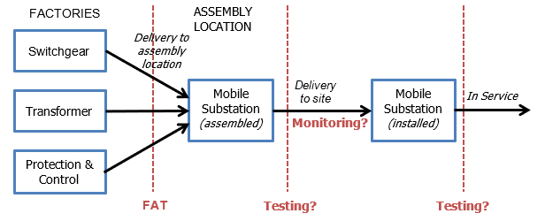
Figure 2 - Testing Locations for Mobile Substations
The WG gives some considerations for the testing of mobile substations regarding the balance between the impact of the testing on the cost and the deployment time and the risk appetite of the user depending on their circumstances (as in the case of emergency situations). This is shown in figure 3.
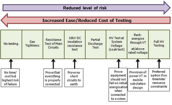
Figure 3 - Risk Appetite and On-Site Testing Options (Note: Tests are cumulative, Left to Right)
Chapter 4 presents some aspects regarding the asset management of the mobile substations such as the storage, the maintenance, the gas handling, the decommissioning of the mobile substation and its later redeployment.
Chapter 5 gives a summary of the in-service experience of mobile substations taken from the experiences provided by the WG members and selected experts. The case studies are described in detail in the Appendices, which are listed here in table 2. A wide range of case studies are presented allowing the reader to refer to comparable experienced to his requirements.
| Appendix | Description | Use |
|---|---|---|
APPENDIX B | Type A – Germany (50Hertz) 380kV, Air bushing connection | System replacement |
APPENDIX C | Type A – USA (Dominion Virginia Power) 138kV, Cable connection | Emergency |
APPENDIX D | Type A – Germany (50Hertz) 110kV, Air bushing connection | System replacement |
APPENDIX E | Type A – Japan (Chubu Electric Power Grid) 66/6.6KV, Air bushing & cable connection | Emergency |
APPENDIX F | Type A –Saudi Arabia (National Grid) 400/132kV, bushing & cable connection | Additional power need |
APPENDIX G | Type A – Ireland (ESBI) 110KV, Air bushing connection | Emergency |
APPENDIX H | Type B – Belgium (Elia) 123kV, Cable connection | System replacement/Emergency |
APPENDIX I | Type B – UK (National Grid) 400/132kV, bushing & cable connection | System replacement/ Maintenance |
APPENDIX J | Type B – Spain (Red Electrica) 220kV, Cable connection | System replacement |
APPENDIX K | Type B – Belgium (Infrabel) 70kV/3DC, Cable connection | Semi-permanent substation |
APPENDIX L | Type C – Germany (50Hertz) 220kV, Cable connection | Offshore |
APPENDIX M | Type C – France (RTE) 63kV, Cable connection | E-House |
APPENDIX N | Type C – New Caledonia (France) 63kV, Cable connection | E-House |
APPENDIX O | Type C – Germany (VMOP) 155/33kV, Cable connection | Offshore |
APPENDIX P | Type A – Japan (User) 77/6.9 KV, Cable connection | Emergency |
APPENDIX Q | Summary of Japanese use |
|
In Chapter 6 the Working Group gives some recommendations for the applicability of existing standards such as the IEC 62271 (high voltage switchgear & controlgear) & IEC 60076 (transformer) series. The Working Group has thoroughly reviewed these standards and found them to be generally suitable for application to mobile substations and it has not identified any requirements for additional mandatory type or routine testing.
In some circumstances, depending on the application, it may not be appropriate for mobile substations to fully comply with conventional standards regarding, for example, foundations, environmental conditions or testing requirements. The Technical Brochure aims to give recommendations on how to consider these topics.
Conclusion
Mobile substations are becoming an established solution and international use is growing. The technology is now considered proven.
The Working Group has identified many cases where mobile substations have been effectively deployed to meet user requirements across a wide range of applications.
Various drivers and benefits have been reported. They can be confirmed by numerous case studies analysed by the WG spanning the range from mobile substations used for emergencies, intermediate type units, and semi-stationary type units. These case studies demonstrate mainly positive experiences, users, manufacturers, and engineering companies have made. Challenges experienced during the projects are also discussed.
Mobile substations are very adaptable to cover different requirements for different applications users may have. To benefit from this flexibility to use a mobile substation according to the specific need in a required time frame, it is recommended to follow the considerations discussed in the Technical Brochure.
This flexibility is also related to risks when transporting, installing, and testing mobile substations on site. This risk situation needs to be understood before energizing the mobile substation. An increased risk appetite can be acceptable in emergency situations where power needs to get restored quickly and time for intensive on-site testing is not available. Previous deployments, known road conditions, shock indicator readings will influence a certain confidence level that needs to be considered for the risk evaluation.
In addition to the risk evaluation, it is important to determine the objective of the use of the mobile substation. A clear understanding of the expected outcome of operating the mobile substation will streamline preparation and mobilization aspects such as choosing the correct mobile substation type, transport options, installation, safety, risks, and on-site testing considerations. Fencing, access, and related safety items should be taken into consideration when operating the mobile substation. A clear objective and good planning will allow the realization of many benefits though using a mobile substation.
Existing technical standards have been reviewed and considered as fit the purpose. There is no recommendation for adjusting or upgrading these standards for the use of mobile substations.
Further details on the recommendations of the Working Group as well as a detailed overview of case studies from a variety of users are discussed in the CIGRE Technical Brochure of WG B3.41.

Other Technical Brochures