Distributed Energy Resource Benchmark Models for Quasi-Static Time-Series Power Flow Simulations
Realizing distributed energy resources (DER) benefits to distribution systems, as well as the overall, depends greatly upon models that accurately represent the performance of these technologies. The rapid evolution of DER technologies and applications, however, poses a challenge for distribution planners and others who must implement representative models for these technologies in their studies. While distribution modelling and simulation capabilities have largely kept pace, the lack of industry-defined reference models has led to inconsistent terminology as well as multiple representations of specific DER types across the industry.
Members
Convenor
(US)
J. TAYLOR
Secretary
(US)
J. PEPPANEN
M. MCGRANAGHAN (US), D. FONSECA (BR), J. SNODGRASS (US), S. CHEN (US), D. MENDE (DE), M. KRAICZY (DE), T. STRASSER (AT), A. BAITCH (AU)
Scope
This Technical Brochure documents a DER benchmark model framework and a set of initial benchmark DER models for quasi-static time-series (QSTS) power flow simulations. Specifically, benchmark models for photovoltaic systems, smart inverters, and energy storage systems are provided – with the expectation that the library of DER benchmark models will be expanded by subsequent Working Groups.
The reasons for specifying the DER benchmark models for QSTS simulation mirror the reasons the simulation type is finding increasing use in planning active distribution systems. While dynamic and EMT simulations allow a more detailed assessment of DER distribution impacts, QSTS simulations are easier to set up and require less expertise and less detailed system and DER models. While EMT models could be used as a reference for QSTS models, this can be problematic for distribution planners who do not commonly perform EMT simulation. Furthermore, benchmarking QSTS models against EMT models is not always practical considering the relatively longer timeframes that are commonly studied using QSTS, which can make comparative reconciliation of the different simulation assumptions, simplifications, and relevant controls difficult.
The framework and DER benchmark models provided in the TB are intended as a common reference for distribution engineers, vendors, academia, and other industry stakeholders to understand and verify the performance of existing models as well as support standardization in industry models.
Description of the TB
The Technical Brochure is composed of six chapters and four appendixes. Following the brief introduction and description of QSTS, provided in Chapter 1, the brochure outlines a framework and requirements for defining DER benchmark models in Chapter 2. Applying this framework, benchmark models for photovoltaics (PV), energy storage systems, and smart inverters are provided in Chapters 3 through 5. The body of the brochure concludes with a vision of the needs and areas for continued development of DER benchmark models in Chapter 6. Additionally, the brochure contains four appendixes capturing supporting information such as code scripts and load profiles in support of the benchmark models.
DER benchmark model framework
This defined framework consists of two key components:
- DER benchmark model structure and
- DER benchmark model specification requirements.
The DER benchmark model structure defines the scope and classification of DER types for benchmark model. This structure ensues the salient DER types are identified and provides the necessary framework that aggregates components and compartmentalizes DER devices at levels that minimizes duplication in the models while readily permitting the combination of DER models to represent installation consisting of multiple DER types.
Recalling the DER benchmark models presented in this Technical Brochure are intended to address distribution system modelling and simulation needs, these models only need to capture DER operation that is interdependent with the distribution system. Aspects extraneous to this relationship can then be represented as equivalents values or inputs.
The scope of DER controls to be included in the benchmarks is also addressed by the structure. While recognized as important to capture in QSTS studies, controls external to the DER device were determined to require their own set of models and similar benchmarking activities are recommended in future efforts.
The model specification requirements describe the key aspects of a DER benchmark model for QSTS simulation. By providing the DER specification requirement, uniformity can be ensured across the different benchmark models provided in this brochure as well as subsequent derivations for other DER technologies. The specification requirements consist of the following:
- Background: Overview of the principles of operation, internal and external factors impacting the DER operation, and the key technology types.
- Benchmark Model: Detailed breakdown of DER model components including source, interface, and control components; descriptions of input variables, output variables, internal parameters, and their relationships; and typical values or value ranges for the model parameters. Example simulation case and results.
- Application Considerations: Discussion of aspects users should be aware of when applying or implementing the DER benchmark model.
Benchmark Models
The TB’s chapters documenting the individual benchmark models follows the previously outlined model specification structure – including an illustrative simulation case with the benchmark model and all system components included in the simulation fully documented. Given the varying composition, operation, and application between DER types, simulation cases were customized to each DER rather than defining a universal test case.
To further illustrate the type of content included in the benchmark section, highlights from the energy storage system (ESS) benchmark model are provided here. The generic model of Figure 1 shows key features of ESS models within a QSTS simulation, including the operating state (idle, discharging, charging), the losses associated with the operating state, energy stored, and the active and reactive power output.
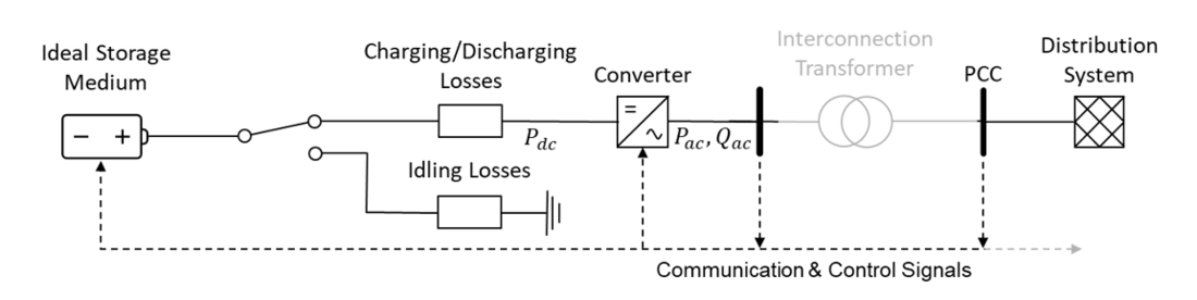
Figure 1 - ESS benchmark model components
Simulation of the benchmark model was performed using the simple network model, shown in Figure 2, consisting of a 12.47 kV distribution feeder supplying two large customer loads and an ESS system. The network information and details on the large customer loads, including their temporal load profiles, are fully documented in the TB. Figure 3 illustrates the ESS operation over a 24-hour QSTS simulation. In this example, the ESS successfully reduced the highest peak loading, factoring in the rating and efficiency, but was unable to keep the main line loading below the target due to insufficient energy capacity. Nonetheless, activating the ESS reduced the duration of the main line overloads from four hours to one hour 15 minutes. The simulation results illustrate the importance of properly capturing the ESS minimum state of charge, as well as operational losses, which resulted in the defined ESS parameters being unable to fully mitigate the line overload in this example. Additional metrics, such as the frequency of the discharge cycle, can also be derived from similar QSTS simulations.
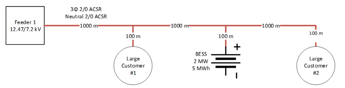
Figure 2 - Network model for the simple simulation example of the energy storage system benchmark model
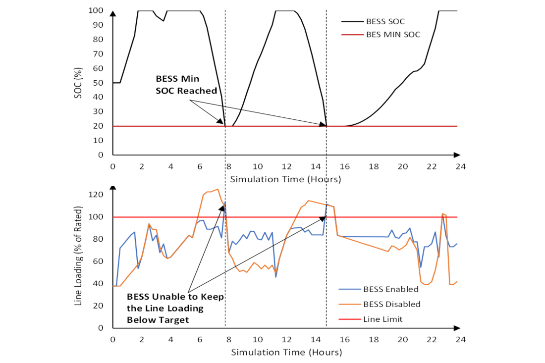
Figure 3 - BESS state-of-charge (top) and the feeder main line loading with BESS enabled and disabled
Conclusions and recommendations
The benchmark models discussed in this brochure represent only a small part of overall industry needs. While great strides have been made in advancing DER models in recent years, these efforts must continue to refine and validate existing models along with developing models for emerging technologies and control schemes. Achieving this objective depends upon the collaboration between electric utilities, researchers, vendors, and industry organizations. This collaboration is critical to realizing the full societal benefits of DER integration while also ensuring electric distribution systems maintain, or improve upon, current levels for safety, reliability, and efficiency.
Areas to be addressed by future Working Groups include:
- Expand the benchmark models to include EV charging, demand response, biomass, wind turbines and other types of DER.
- Expand the DER benchmark models from autonomous controls to centralized controls by advanced distribution management systems (ADMS) and DER management systems (DERMS).
- Validate the DER benchmark models against laboratory and field testing of DER.

Other Technical Brochures