Advances in the interpretation of transformer Frequency Response Analysis (FRA)
Measurement of winding frequency response is now commonly used to assess the mechanical integrity of the active part of power transformers. The analysis of the results, so-called Frequency Response Analysis (FRA), is based on comparison with a reference measurement which is either a previous measurement on the same unit, a measurement on an identical transformer, or a measurement on another phase of a three-phase transformer.
Convenor
(CA)
P. PICHER
TF1 Leader
(DE)
S. TENBOHLEN
TF2 Leader
(US)
M. LACHMAN
TF3 Leader
(BR)
A. SCARDAZZI
TF4 Leader
(US)
P. PATEL
N. ABEYWICKRAMA (SE), B. DIGGIN (IE), S. GAZIVODA (HR), R. GRUENSEIS (AT), D. JU (CN), V. LARIN (RU), J. LI (CN), M. LOCARNO (US), H. MARTINS (BR), S. MIYAZAKI (JP), M. RAEDLER (AT), J. SANCHEZ (FR), Y. SHIRASAKA (JP), B. SZTARI (HU), M. TAHIR (DE), R.K. TYAGI (IN), J. VELASQUEZ (DE), Z.D. WANG (UK), M. WEBER (DE), P. WERELIUS (SE), R. ZALESKI (PL)
Corresponding Members: R. ALVAREZ (AR), R. AMINI (IR), O. AMIROUCHE (IT), J. BORGHETTO (IT), H. RAHIMPOUR (AU), D. SOFIAN (UK), J. TUSEK (AU)
Other Contributors: E. ALZIEU (FR), B.Z. CHENG (UK), P.A. CROSSLEY (UK), R.S. FERREIRA (CA)
In 2008, CIGRE published a Technical Brochure (TB 342) [1] on the assessment of the mechanical condition of transformer windings using Frequency Response Analysis (FRA). This guide covers the various measurement techniques available in the industry and makes recommendations on the standardization of good measurement practices. One chapter is dedicated to FRA interpretation and several examples of frequency response measurements and diagnostics are reported.
After the CIGRE Working Group had completed their work, an IEC project team was initiated to develop a standard on the measurement of frequency response. The standard, published in 2012 [2], largely based on the previously published CIGRE guide, specifies the measurement method (connection and configuration), the measuring equipment and the measurement records.
In parallel with the CIGRE and IEC initiatives, another working group was active within the IEEE. The measurement configurations presented in the IEEE guide [3] are generally similar to those presented by IEC, but there are a few differences in the recommended configurations for a new set of measurements.
Even if the method has recently been studied at the international level in various working groups under the umbrella of the CIGRE, IEC and IEEE organisations, there was still a need in the industry to obtain more guidance on the interpretation of the results. In fact, the usual way to interpret the result is to visually and subjectively compare the frequency response curves and make an interpretation based on previous experience. The ultimate goal would be to develop an internationally agreed objective interpretation algorithm that can be applied to condition assessment of transformers after an in-service event, or as a pass-fail criterion for transformer short-circuit testing.
In this context, CIGRE WG A2.53 was created in 2016. The resulting Technical Brochure (TB) covers the following topics:
- General and fundamental understanding of the frequency response.
- Factors that can influence the measurement and therefore the interpretation.
- Case studies showing how FRA can be used to detect mechanical failure modes and other electrical failures.
- Literature review of quantitative FRA assessment. An interim report on this subject was published on behalf of the WG [4].
- Evaluation of numerical indices performance over key technical parameters using academic experiments with controlled winding mechanical displacements and selected WG A2.53 case studies.
Understanding of the frequency response
A transformer frequency response is a representation of the interactions between the inductance, capacitance and resistance elements comprised in the circuit model of the windings. This is discussed in two chapters of this technical brochure. The first chapter aims to provide the reader with a basic understanding of the main features that can be expected in a frequency response measurement. It presents a description of the physics behind frequency response and a description of typical responses depending on different winding designs and configurations. The second chapter provides a more in-depth discussion through transformer circuit modelling.
A transformer can be modelled as its equivalent circuit network, consisting of a combination of elements which are geometry dependent. Windings for the same phase are magnetically coupled, and represented by self and mutual inductances. In addition to the winding series capacitances and shunt capacitances to earth, a pair of adjacent windings is also electrostatically coupled, resulting in inter-winding capacitances. Consequently, there is a relationship between winding geometry, equivalent electrical components of the circuit network and the measured frequency responses at the winding terminals.
The underlying diagnostic principle of FRA is that a physical displacement or deformation of windings results in changes in the equivalent electrical components of the corresponding winding part. These changes are reflected in changes or even additions to the observed resonant frequencies observed in frequency response curves.
Factors influencing the measurement
For frequency response measurements, the likelihood of a transformer having a problem is significantly lower than the likelihood of the test personnel making a mistake. The section reviews the factors potentially influencing the data. With the presented examples, the objective is to raise awareness about the role these factors may play so that in searching for causes of abnormal data, their potential contribution is not overlooked.
These factors may be due to the measurement setup, the transformer state (e.g., temperature), the transformer configuration (e.g., tap position), or external factors. Once these factors are eliminated as suspects or identified as not relevant, attention can be turned to the transformer.
Case studies
A selection of 18 case studies from a total of 60 cases collected by the WG is presented in the TB. These examples illustrate the frequency ranges that relate to the different failure modes. However, it can be inferred from the small number of cases shared at the international level that experience is very limited in FRA interpretation where there is a clear correlation with a mechanical failure. This could be due to multiple failure modes playing a role when a winding is compromised. For instance, if a winding is subjected to mechanical displacement, this is likely followed by a turn-to-turn failure, which can be detected using conventional electrical tests. Mechanical displacements without turn-to-turn failure are often investigated by dismantling the active part to identify a mechanically damaged winding; this is often the winding closest to the core. Since such post-mortem investigations are costly, they are not common practice and potentially good case studies are being lost. It is also possible for a transformer to survive the mechanical displacement of a winding and for this weakened condition to go unnoticed due to lack of testing and inspection.
As demonstrated in the case studies, the appearance of new features or major frequency shifts is cause for concern. Significant changes of the trace amplitude are usually accompanied by significant phase differences, so phase information is to some extent redundant. In this TB, only the amplitude information is used for the analysis. The case studies measurements are assumed to have been correctly executed using the best recommended practices.
The following main mechanical and electrical failure modes are presented in the case studies:
- Buckling
- Twisting and loss of clamping
- Axial displacement
- Conductors tilting
- Lead movement
- Spiralling
- Short-circuit inside winding
- Broken core earthing
The TB also presents some examples of frequency response measurements performed before and after short-circuit tests.
Literature review of quantitative assessment
FRA is a comparative diagnostic method which needs a reference for comparison. Different methods are described in the literature to quantify the variation between a new trace and a reference measurement. These methods can be categorized into three main groups:
- algorithms based on numerical indices
- algorithms based on a white box model
- algorithms based on artificial intelligence (AI)
Numerical indices quantify the differences between reference and present frequency response traces using mathematical equations. The equations normally use the amplitude of the frequency response to calculate the value. Some numerical indices are calculated directly using the trace data values and others are based on the resonance frequencies or vector fitting of the traces.
Algorithms based on white-box models aims to model the frequency response either using a circuit model to explicitly describe the inductance, capacitance and resistance topology representing the windings or using finite element modelling (FEM) to reproduce numerically the electromagnetic behaviour of the windings. In general, circuit and FEM models need details of the internal geometry which are usually not available for all transformers. They are then mostly used by academic institutions to study FRA and by transformer manufacturers to optimize their winding design for dielectric performance. The 3D FEM approach is useful to generate data for developing FRA interpretation, for instance simulating the various mechanical failure modes or studying the effect of windings electrical properties on the frequency response of transformer.
Some methods estimate the elements from only the terminal measurements. It is possible to extract physical parameters from the frequency response measurements (e.g. leakage reactance, turns ratio, capacitance, etc.) and compare these numerical values with a previous reference measurement. This approach does not require a detailed knowledge of the internal geometry and is thus applicable for general FRA applications.
There are several AI algorithms, e.g., decision tree, fuzzy logic and neural networks, and each one has its own characteristics. Some researchers use such methods to estimate the parameters of a transformer’s high-frequency model from data obtained from frequency-response measurements. Some other researchers implement AI techniques for the recognition of frequency-response patterns of the winding to detect any failure of the internal winding insulation. In this regard, the fault type is also determinable by means of frequency response classification through AI methods. AI algorithms can use a combination of several indices for such classification. A database, not generally available, is required to train the models. Some contributions propose using the outputs of circuit models of FEM as a database. However, the applicability of these models for a transformer fleet is itself an issue.
Evaluation of selected numerical indices
The numerical indices analysed in the TB are calculated directly from the trace data values (amplitude and phase) as they are the easiest to implement. The numerical indices were evaluated using academic experimental models with several steps of axial and radial deformations and using selected case studies from our WG database.
The results show that different indices behave differently within each evaluation criterion (monotonicity, linearity, sensitivity, and data size dependency). The definition of the frequency ranges for interpretation is challenging because it depends on many factors related to the transformer design. A new approach using a sliding window, as illustrated in Figure 1, resolves this problem. The deviation between frequency response signatures is then calculated as a function of frequency. An implementation of this approach demonstrated a good sensitivity to detect deformed windings on several cases from the WG database.
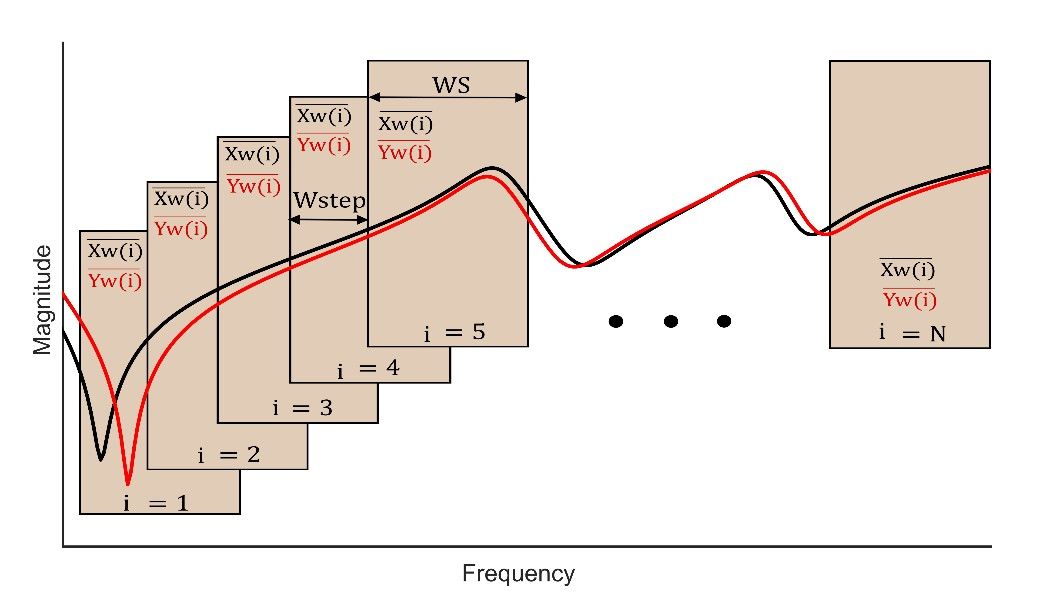
Figure 1 - Implementation of quantitative FRA interpretation using the sliding window method
Conclusion
This TB contributes to the improvement of FRA interpretation by collecting industry experience and contributions from academic institutions. In conclusion:
- The basis for FRA interpretation is the understanding of the frequency response and the factors that can influence the measurement.
- The selection of case studies presented and analysed in this document can be used as reference examples to show how a mechanical displacement can be detected using FRA.
- Academic contributions help complement the limited number of real case studies data with laboratory investigations and numerical modelling.
- The WG agrees that it is still too early to make a definite recommendation for FRA quantitative assessment using quantitative criteria and thresholds.
- Based on academic contributions and an analysis on selected case studies, some indices were identified as the most promising for further investigation.
The WG recommends that:
- CIGRE continues to offer forums for sharing case studies of FRA interpretation (workshops, preferential subjects, etc.).
- The international transformers community uses the most promising indices for further development of objective FRA interpretation.
- Academic institutions continue to support FRA interpretation related research.
- [1] CIGRE WG A2.26, "Mechanical-Condition Assessment of Transformer Windings Using Frequency Response Analysis (FRA)," CIGRE Brochure 342, 2008.
- [2] IEC 60076-18, "Measurement of frequency response," 2012.
- [3] IEEE Std C57.149-2012, "IEEE Guide for the Application and Interpretation of Frequency Response Analysis for Oil-Immersed Transformers," 2013.
- [4] P. Picher, S. Tenbohlen, M. Lachman, A. Scardazzi, and P. Patel, "Current state of transformer FRA interpretation: On behalf of CIGRE WG A2.53," in Procedia Engineering, 2017, pp. 3-12.

Other Technical Brochures