Magnetic core dimensionning limits in hydro generators
Under the title Magnetic core dimensioning limits in Hydro-Generators, Working Group A1.49 has undertaken the task of demystifying the theoretical approach of dimensioning the magnetic core of salient pole synchronous machines.
Convenor
(BR)
JJ. ROCHA E.
Secretary
(CA)
A. MERKHOUF
A. SOLUM (SE), C. KREISCHER (DE), E. BORTONI (BR), E. MINEMATSU (JP), E.A. KAGGESTAD (NO), H. ISHIZUKA (JP), H. MATSUMOTO (JP), J. KIM (KR), K. MOLOSE (ZA), K. FUJIWARA (JP), M. BRCIC (HR), M. GIESBRECHT (BR), M. UEMORI (BR), P. WIEHE (AU), P.N. THIABAUD (FR), R. TREMBLAY (CA)
Corresponding Members: L.L.H. COSTA (BR), R. PERERS (SE), T. HILDINGER (BR), C. HALUSKA (BR)
We believe that the understanding of magnetic core dimensioning limits demands knowledge of the theory of magnetic circuits applied to hydro-generators. For this reason, the Technical Brochure was developed as a consolidation of history, papers and several books.
To conduct this task, certain premises were stated related to technical documentation in general:
- The bibliography should be in public domain;
- State a transparent evolution of formulation throughout the text;
- A computational program will not be delivered as an output, although all the formulation was programmed, and the results were fully validated;
- As an Annex of the technical brochure, a benchmark model will be introduced with calculated results aiming to support the elaboration of customized routines.
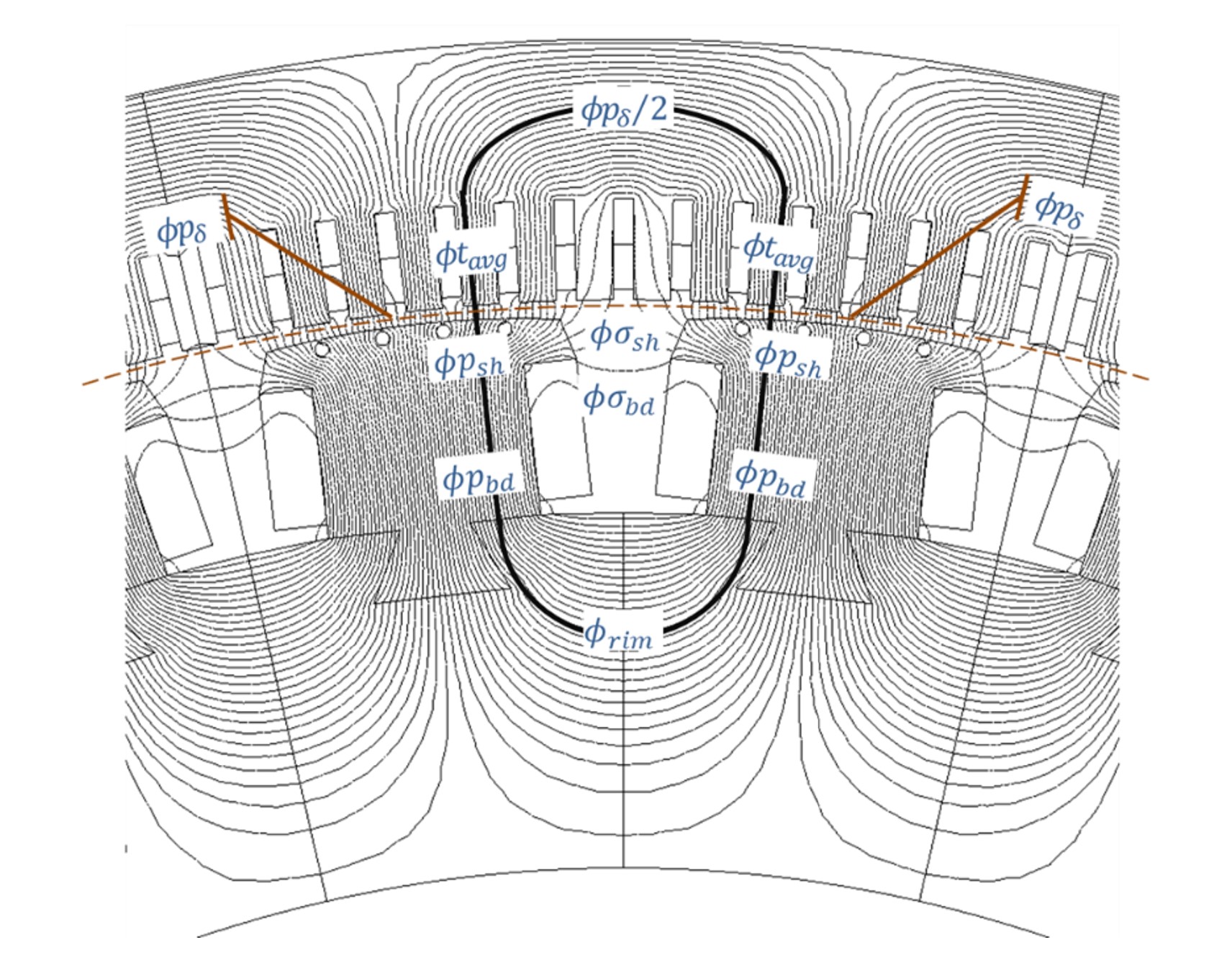
Figure 1 - Magnetic flux lines distribution in no-load conditions
Structure of the Technical Brochure
After finding a detailed magnetic circuit theoretical exposition, based on Figure 1 the reader is introduced on the universe of magnetic flux leakage which approach is very hard to find in traditional books or papers. As illustrated Figure 2, from a 1903 paper the concept of “leakage-flux-tubes” was extracted. This is an attempt to confine the dispersed leakage magnetic flux (like ϕσsh and ϕσbd in Figure 1) inside of imaginary tubes where they can be quantified.
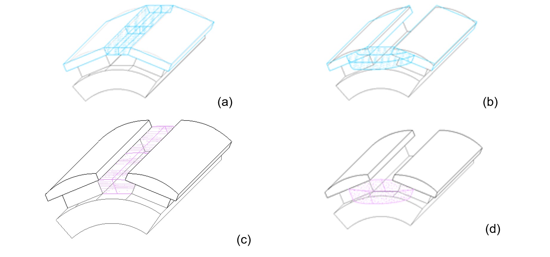
Figure 2 - Magnetic tubes of leakage flux (a) and (b) represent ϕσsh the leakage flux-tube in pole shoe; (c) and (d) the leakage flux-tube in pole body.
Once the concept of pole leakage coefficient is clearly defined, the procedure for calculating no-load excitation current is introduced. With that, the theory is extended to calculate the machine no-load characteristic.
As saturation is highly dependent on material properties, an exhaustive analysis on the real nature of silicon-steel sheets is developed for stating the “state of the art” of its properties, revisiting the concept of anisotropy. As shown in Figure 3, this analysis demonstrates that non-grain-oriented silicon steel is actually isotropic whose impact in the excitation current calculation may elucidate some “inexplicable” deviations.
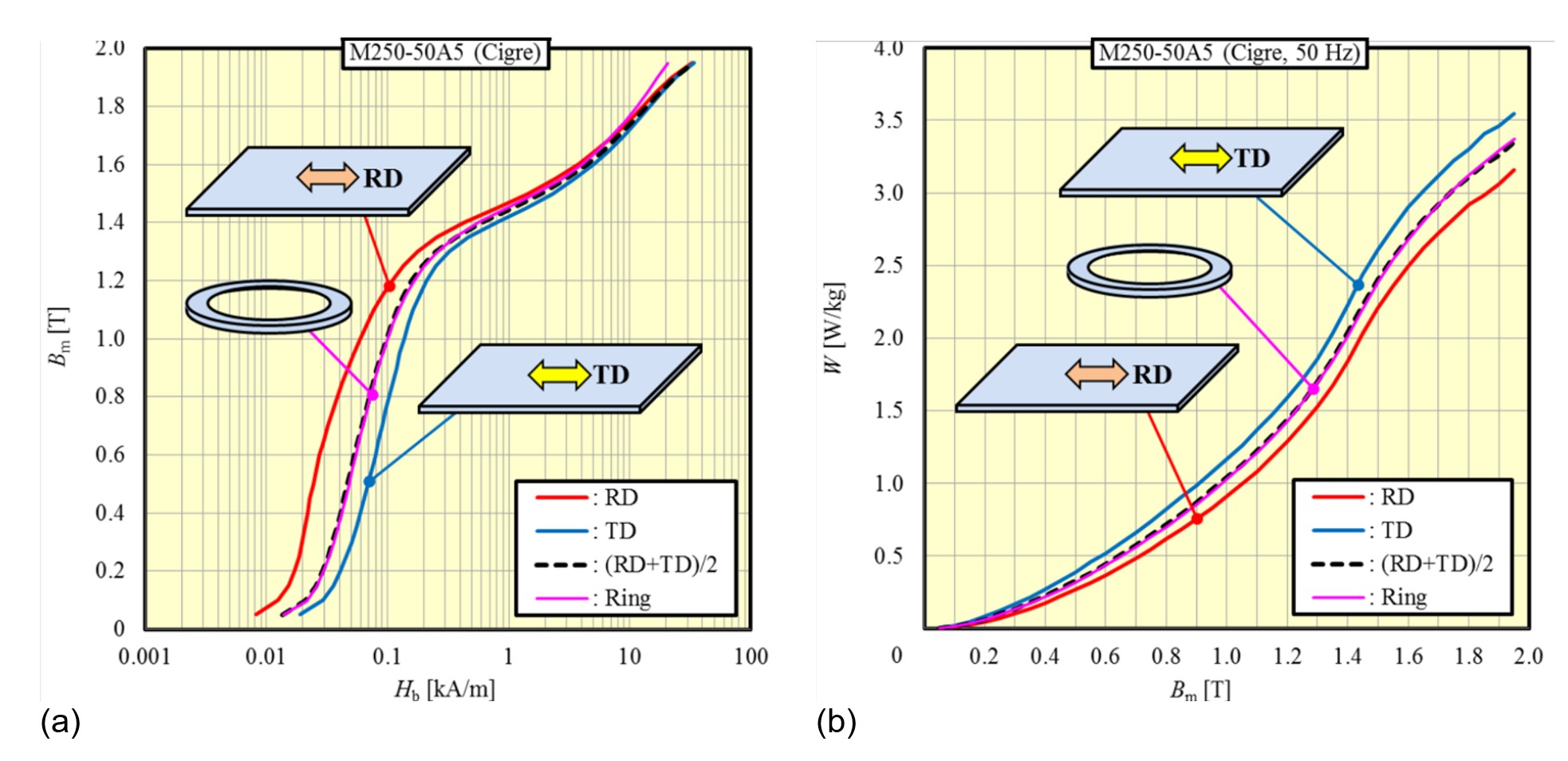
Figure 3 - Anisotropy in NGO M250-50A5 (a) Magnetic properties and (b) core loss
Complementarily, the application of grain-oriented silicon steel is debated. The pros and cons are tabled based on practical applications.
As it can be appreciated in Figure 4, a saturation index is presented as the conjugation rate of two excitation current points. The one over the air-gap line (If0) to the other over the saturation curve (Ifg), both at rated no-load voltage. The goodness of this proposed index lays in the fact that these two excitation points are commonly informed in every technical machine description.
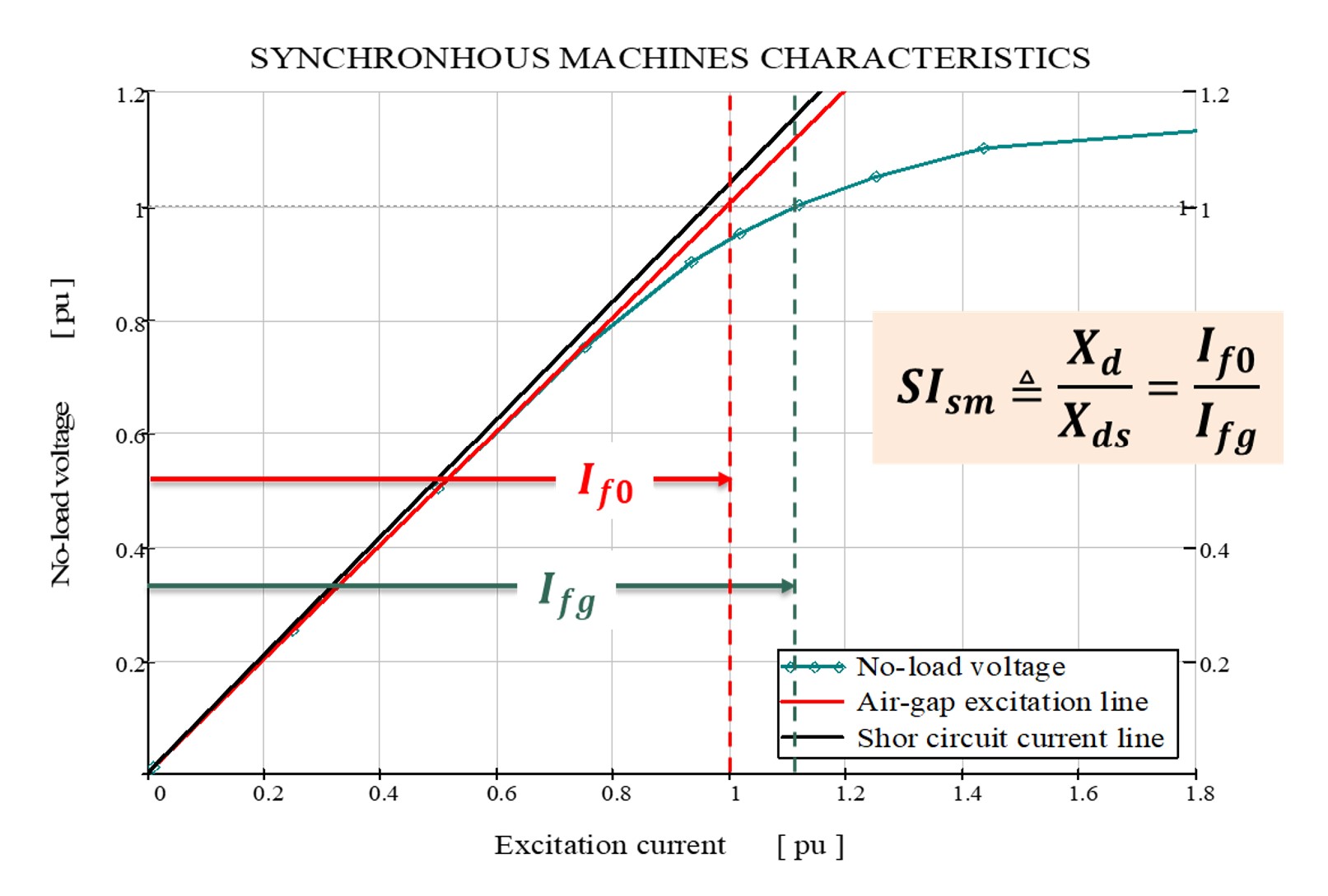
Figure 4 – Synchronous machine Saturation Index definition
Finally, aiming to motivate the reader to implement his own calculation routine, as an Annex to the Technical Brochure is presented:
- A benchmark reference machine data;
- The pole magnetic flux density over the air-gap line and its Fourier series harmonics;
- Typical core materials magnetic characteristics; and
- The benchmark machine expected results.
Conclusion
The author’s hope is to contribute to a better understanding of salient pole synchronous machine magnetic dimensioning analytical process.

Other Technical Brochures