Protection and automation issues of islanded systems during system restoration/black start
There is an increase in wide-scale blackouts due to the increase in natural disasters events, increased grid interconnectivity and load and generation mix change. Quick system restoration, after a widescale blackout, is becoming increasingly necessary as we move towards increased electrification of process-heat and transportation load to meet low-carbon energy systems. Based on blackout postmortems, system restoration has been observed to be delayed resulting from protection equipment operation which in certain situations behaves differently during restorative conditions. These unintended protection actions could cause coordination delays that could eventually lead to other lengthier restoration plans (out of the many options to reenergizing core grid) experienced following a large-scale blackout event.
Convenor
(NZ)
N. NAIR
Secretary
(NZ)
R. SHAW
Secretary
(NZ)
D. KANIARU
A. OOMMEN (ZA), D. KAMENSCHIKOW (DE), M. LIZER (PL), F. COFFELE (UK), M. ENNIS (US), A. BARTYLAK (ZA), B. SHI (CN), C. BOOTH (UK), G. LLOYD (UK), M. FAZLALI (SE), J. MARQUES DE LIMA (BR), H. LAAKSONEN (FI), T. FOXCROFT (AU), G. HURFORD (ZA), I. TSHWAGONG (ZA), L. NAIDOO (ZA), B. CHRISTISON (ZA), S. JOSEPH (ZA), A. HARJULA (FI)
This ELECTRA article provides a high-level summary of WG B5.54 of which its objective was to investigate protection and automation (P&A) issues that may lead to delay in implementing the network restoration procedures. Progression from when a blackout starts to when normalcy resumes is as shown in Figure 1.
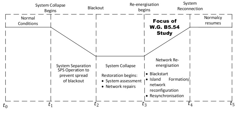
Figure 1 - Time-period under consideration
Focus of this Working Group is on the network re-energization stage. The Working Group members took into consideration the earlier CIGRE Technical Brochures that includes:
- WG 38.06.04: Use of expert systems for power system restoration - BT 090
- WG 34.08: Isolation and restoration policies against power system collapse - BT 200
- WG 39.01: The needs and environment of control center operators during power system restoration. A benchmark questionnaire survey - BT 208
- WG B5.34.01: Auto-reclosing and local system restoration - BT 270
- WG C2.23: System restoration procedure and practices - BT 712
Most of the works above focused on restoration from a strategic viewpoint looking at restoration policies and procedures. Only WG B5.34.01 focused on auto-reclosure operation but from a distribution network point of view. This led to most transmission and distribution utilities developing restoration plans and sequences after occurrence of a blackouts. However, recent large-scale disturbance has highlighted delay in restoration procedures are a result of protection maloperation during network re-energization:
- USA/Canada 2003 Blackout: Resynchronization challenges due to voltage disparities
- Italy/Switzerland 2003 Blackout:
- Loss of telecommunication and SCADA thus no visibility of the network
- Resynchronization challenge when connecting 2 weak islands due to large standing phase angles
- Brazil/Paraguay 2009 Blackout: Resynchronization challenge of generating units ready to assist in load pickup
- India 2012 Blackout: Operation of generator reverse protection as it tried to maintain an island
- Turkey/Bulgaria 2015 Blackout: Unintended Operation of a special protection scheme disconnecting the tie lines between Bulgaria and Turkey
- Australia 2016 Blackout: Transformer protection operation on inrush current
For the above disturbance cases, it is necessary to assess and understand the issues observed network re-energization primarily from a protection and automation perspective.
Description of the Technical Brochure
This Technical Brochure (TB) has integrated three strands of contributions based on the body of technical knowledge, working group member experiences and curation of technical contributions arising from a survey conducted and Special Report. 80% of the TB is based on contributions made from the members while 10% is a summary of a survey that was undertaken to investigate specific P&A issues experienced during restoration. The remaining 10% summarizes relevant contributions made from 2018 B5 PS1 under the topic ‘Protection Under System Emergency Conditions’ of which the convener was the special reporter. All these have led to the development of seven chapters of this TB of which Chapters 1 and 2 provides a review of work previously undertaken on this topic and case studies that support the scope of work of this working group respectively. This has already been summarized in section I of this paper. Subsequent discussion of this ELECTRA paper is based on the other contributing Chapters 3-6.
Restoration practices
Different strategies can be used in re-energizing the network after a wide-scale blackout depending on the nature and trajectory of the blackout. The most common strategy of most utilities with regards to network re-energization is to first start the designated blackstart generator, build up network islands centered around the blackstart generators and synchronize the built-up islands. This is shown in Figure 2.
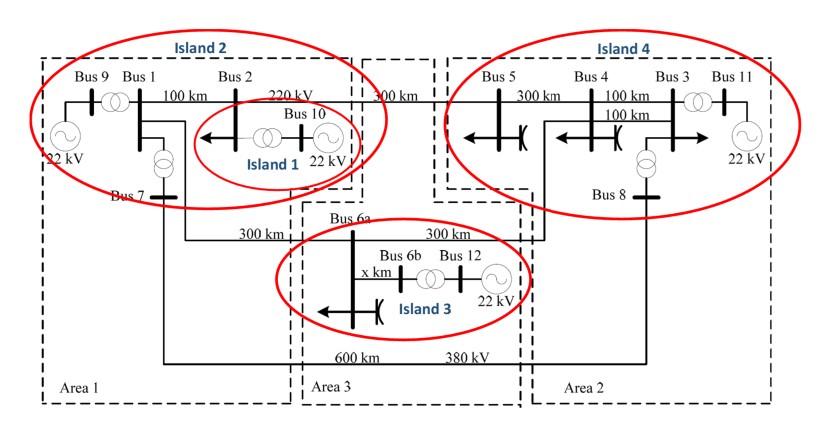
Figure 2 - Example of an Island Formation Process using CIGRE Transmission Benchmark model
If this strategy fails, regional tie-lines from already energized networks or from networks that were not affected by the blackout, are used to re-energize the network. This was the case for most of the case studies described in section 1.
With regards to blackstart generators, hydro power plants require less than 1% as auxiliary power thus they are preferred for blackstart as compared to thermal power stations that require 10% of their capacity as startup power. However, thermal power plants equipped with load rejection capabilities can be used with the condition that it should be loaded to minimum load as quickly as possible as large coal-fired generators operate safely and stably at 50% loading. Most units require oil burners to stabilize the boiler below 50% loading and it is during this time that the unit can become unstable. It is therefore imperative to load the units to a point where it does not rely on oil burner support. Substations must be prepared and sectionalized before re-energization of the substation or network. Following a blackout, all substation breakers will still be closed, and it is imperative to note that preparing a substation for initial restoration is one of the most crucial parts of restoration. Before designating a substation for re-energization, the following should be taken into consideration:
- Time the AC supply has been off;
- State of the DC supply at the station;
- Risks associated with first energization;
- Voltages at the end of the lines connected to the substation as a result of Ferranti;
- Availability of sufficient reactive power absorption capabilities to ensure no generators exceed their under or over excitation limit when a line/substation is energized.
Substation auxiliary equipment, which are DC components, are required to be available even if the transmission power is not available. All grids have standby DC generators kept at a central location. These generators can be used at sites that may have DC problems during restoration. A DC conservation plan is required to save the available power as restoration continues. The plan looks at all DC loads at a station and what can be done to prolong the life of the batteries with no AC supply. The typical battery availability at transmission stations is about 8 to 12 hours depending on their age. It is therefore vital to ensure that instructions are given to all substations on the day as to what DC conservation plan is to be followed. It is important to note that with the station DC switched off there will be no SCADA or Voice communication to the station. This will have an impact because when the station becomes ready for energization, grid staff will need advanced warning to get field personnel to site to switch the DC on.
When restoring load there are many factors that need to be taken into consideration. It is recommended that during initial restoration smaller load blocks are used. Once the bigger units start to synchronize, the load block sizes can be increased. Before this happens, the controller needs to be aware of the type of load that is being restored. The three main load types in this regard are residential, Commercial/semi-industrial and Industrial. Each type of load has its own unique characteristics, and during restoration there is a trade-off between the different load types. For example, residential load will always be available after a fault, (but there are issues with cold load pick up), whereas industrial load takes a significant amount of time to start their processes (up to 8 hours) and does not have the problem of cold load pick up.
Voltage and frequency control
Voltage control during system restoration is much more complex as compared to voltage control in a healthy system. In a healthy system, the fault level is high at stations near or at power stations and reduces further away from the power stations. The fault level of the system is dependent on the number of generators connected to the system. During system restoration, the fault levels are at minimum during the initial phases of restoration. This is due to the limited number of generators connected to the grid at the time. The fault level increases as each generator synchronizes to the island. With low fault level a small change of reactive power (MVArs) will result in a high change of voltages. Reactive power devices such as reactors, capacitors and static VAr compensator (SVC) will behave very differently during system restoration due to the lower fault levels.
Frequency control is also much more complex in restorative state. In a healthy system, the frequency bias is dependent on the amount of generation on-line and the amount of generation reserves that are available from those generating units. In a power system that has been built up from one generator, the frequency bias will be much lower. The actual amount will depend on the number of generating units on-line together with the generation reserves within the island. Automatic Generation Control (AGC) will also not be available for the duration of the restoration process. It is always good practice to run the frequency a little higher when restoring load, however it must still be kept to within limits. The reason for this is that the frequency will go lower with additional load. When additional generators are to be synchronized onto the island, the island frequency is proposed to be reduced to below 50 Hz before the new generator synchronizes into the island. This can prevent a high frequency event should the generator being synchronized, be operating at high load.
With regard to generator control modes, the operators need to understand the different control modes of the generators in their network as power plants are able to switch between different voltage and frequency control modes. The speed control of power plants especially in the beginning of the restoration process should be able to handle load step changes. Governor speed response is usually configured in such a way that there is a fast speed response to load or system changes. However, when in system restoration or islanded situation, the inertia is much lower, and the governor response can cause instability. The governor is proposed to be set to a slower response to avoid speed hunting with increasing speed oscillations. To reduce inrush currents, the exciter of black start units should be able to increase the generator voltage slowly while energizing lines and transformers. Furthermore, the starting point when starting re-energization should be as low as possible. After the process of increasing the generator voltage, the AVR is recommended to be switched to voltage control mode. This is important to avoid voltage deviations after loads or lines re-energization or also starting motors in other power plants. Shunt reactors can be used to compensate the capacity of the lines to avoid underexcitation of the black start unit. In some cases, hydro power plants generators have to use a pilot exciter to reach a certain voltage level before use the common exciter. The limited reactive capability curve of the generator using a pilot exciter has to be considered during black start.
Simulation and testing
Black-start restoration procedures should be thoroughly verified during simulations to ensure that the procedure is feasible, safe and it does not carry any hidden risks. Simulations provide valuable information about system behavior in both normal and extreme conditions, allowing analysis on relevant phenomena that could hinder restoration. Simulations also allow to develop better understanding of all potential risks and to make adjustments to the procedures where necessary. There are three common forms of simulations:
- Steady State Simulations for load flow and fault level studies
- Dynamic Simulations for transient stability and fault ride through studies
- Electro-Magnetic Transient Simulations for insulation coordination and Subsynchronous Resonance (SSR) Studies
Steady state simulations are used to check the generation-load balance of the forming islands. Dynamic simulations, on the other hand are used for fault studies and checking the stability of the formed islands. EMT studies are used to analyze overvoltages, ferroresonance, Transient Recovery Voltages, and detailed protection performance. To ensure high quality of dynamic evaluation, accurate models of the system components that will participate in the initial stages of restoration are required. The system model for black-start evaluations requires only few system elements that take part in system restoration, so the model is not extensive but requires high degree of precision to be able to reflect all network phenomena that need to be analyzed.
The time domain simulations must follow step-by-step restoration procedure including occurrences of short circuits in every step of restoration for evaluation of switching transients and protection performance. Detailed EMT simulations are required up to a stage when at least the first big commercial generator is synchronized to the network that was started from a dedicated black-start facility and significant amount of load has been picked-up. The level of load that should be available on black-started island to assume normal electromagnetic behavior of the island depends on voltage level of transmission system and sizes of generators and transformers on the network. As an example, on 400kV network with 600MW generator started from black-start facility and 500MVA transmission transformers on the network a 100MWs of load can be considered sufficient to assume that the electromagnetic behavior of the network will not be abnormal. On the other hand, on 132kV transmission network with 60MWs generators and 50MVA transformers, 10MWs of load can be considered adequate. In general, the level of load (resistance) required on the island has to be sufficient to provide adequate damping of switching transients and ferroresonance.
Periodic black-start facility tests are done in line with local Grid Code or any other relevant statutory requirements that are applicable from electricity regulation perspective. Due to complexity of live black-start tests and costs involved, it is common to separate black-start tests requirements into so called partial tests and full tests. Partial test involves starting up of the unit from an independent source and energizing a defined portion of the transmission/distribution system whereas a full test is extended to loading of the unit to prove black-start capability. For full testing, it is usually better to choose a single Customer with sufficient and well-defined load to simplify coordination and communication efforts. Once the Customer agrees to participate in the black-start test, all the risks associated with the customer have to be identified and discussed.
Generator related protection and automation
The main issues that have been identified with regard to generator protection are in relation to the power swings and abnormal voltages that might be experienced during restoration. Abnormal voltages are as a result of energization of long unloaded transmission lines while power swings occur in multi-machine power systems as an effect of imbalance of the synchronous generators mechanical power and their active power load. Such disequilibrium may appear after short-circuit during grid reconfiguration when re-energizing the network. This phenomenon may influence the operation of the protection and automation systems of network elements.
1) Out of step/Pole slipping
The out of step relay (designated by ANSI number 78) detects the generator asynchronous power swings on the basis of the impedance trajectories transition through the protection characteristic detection, as showed on Figure 3. Typically, the 78 protection settings are based on the generator sub-transient reactance Xd’ (as Zb on Figure 3), step-up transformer reactance XT (as Zc on Figure 3) and the grid equivalent reactance Xeq (as Za on Figure 3 (a) and Zd on Figure 3 (b)).
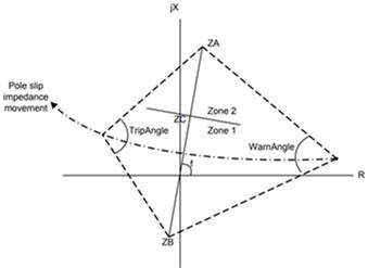
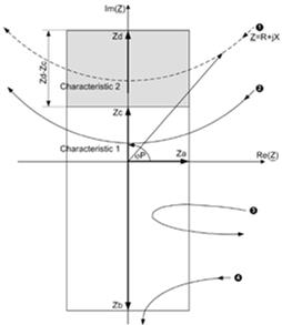
Figure 3 - Typical lenticular (a) and rectangular (b) characteristics of the generator out-of-step protection
The protection characteristic is typically divided into two zones. Zone 1, specified by the Zb and Zc vectors, detects the power swings impedance trajectories transiting through the power unit elements equivalent reactance. In such a case the power unit is disconnected from the grid after the first power swing (when the impedance trajectories exit the 78-protection characteristic coming from its right to left borders). Zone 2, specified by Za (on Figure 3(a)) or Zd (on Figure 3 (b)) vectors, detects the power swings trajectories passing through the grid equivalent reactance. Typically, in such case, the 78 protection trips after the second power swing detection. As the Xeq value is changing in relation with grid configuration and conditions, typically the Za (on Figure 3(a)) or Zd (on Figure 3(b)) parameters of the 78 function are set in relation with grid operational minimum short-circuit power (grid operational maximum equivalent reactance).
During system restoration, the grid short-circuit condition may be very weak so the possibility of power swings in such condition may be relatively high. In such circumstances proper operation of power swing blocking algorithms is crucial as their ‘missing blocking’ may lead to unwanted tripping of the underimpedance and distance protection relays in the grid what can cause HV lines and power units shutting off and this will prevent the grid restitution. From the other side, power units cannot operate in the asynchronous conditions. Because of that, selective and sensitive operation of the generators out-of-step protection is very important during blackstart of the grid.
2) Undervoltage protection
Typically, power unit protection system contains the undervoltage protection (27), which is provided to detect the lowering of the power unit voltage that is an effect of deficit of reactive power in the network. As a result, power units load drives rotors may stall (typically when the house load voltage decrease bellow 0,8 Un), leading to insufficient efficiency of the thermo-mechanical part of the power unit causing the unit to completely shut down for a long period of time. Because of that, power unit undervoltage protection is provided. It measures the voltage at the power unit HV or MV side and if it drops below the set threshold, the protection trips leading to power unit disconnection from the grid. With such operation, power units drives will be able to stay in correct conditions, and it will be possible to quickly reconnect the power unit with the grid. Correct operation of the power unit underimpedance protection is especially important during system restoration.
Most of the power units house load (auxiliary) transformers are equipped with on-load tap changers (OLTC), that are able to improve the voltage conditions. Operation of the OLTC has its own dynamic and it should be considered during setting up of the power unit undervoltage protection. Example of the simulation studies results showing the voltage levels at the network (400 kV), generator terminals (15 kV) and the power unit house load bus bars (6 kV) are shown in Figure 4.
During the network voltage collapse, the generator voltage regulator was able to keep the stator voltage and also the house load voltage at the nominal level for approximately 26 s from the start of the voltage collapse, when the network voltage reached approximately 0.9Un level. After that part, the generator AVR regulation limit was reached and its terminal voltage also began to decline. From that moment, the auxiliary transformer OLTC operates allowing to maintain a higher level of the house load voltage relative to the generator voltage. With that, 0.8 of the nominal level of the power unit house load voltage is reached much later than the network or generator voltages reach that relative level.
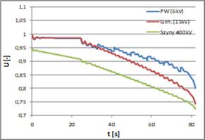
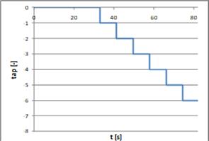
Figure 4 - Network (400 kV), generator terminals (15 kV) and power unit house load bus bars (6 kV) voltage levels (a) and OLTC position (b) during voltage collapse
Keeping that relation in mind, power unit undervoltage protection 27 pickup setting should be chosen with relation to voltage measurement localization and OLTC dynamics. If the 27 function measures the house load voltage it may be set to 0,8 Un and should operate within typically 10s. If the function measures the voltage in the generator terminals, it should be set a little lower, for example to 0,75-0,78 Un (0,78-0,8 Un if no OLTC is used). If the voltage is measured in the HV side of the power unit, the 27-function setting should be set even lower – approximately to 0,73-0,75 Un (0,76-0,78 Un if no OLTC is used). Such approach allows to keep the power unit in the grid during the network voltage instability as long as it is safe for the power unit house load drives, which are very important during blackstart of the grid after system failure.
3) Loss of field protection
There is need to review the coordination between loss of field protection (LOF) and under excitation limiter (UEL) under low voltage conditions. The LOF is usually set on the R-X diagram while the UEL is set on the P-Q diagram, both under nominal voltage conditions. Under low voltage conditions, there might be an overlap between the two thus causing miscoordination.
Transmission related protection and automation
Depending on the blackstart stage and fault position, fault currents during blackstart restoration vary from few hundred amperes to few kilo-amperes. The first and most important check is to make sure that at least some protection functions either main or back-up will be able to detect faults until fault level increases in line with restoration process. Fault duration may be compromised to some acceptable extent due to low fault currents and limited impact on generators’ stability in low loading conditions. In every step of restoration, the dependability of protection systems on energized circuits should be verified. Static simulations for a specific fault are therefore sufficient.
1) Impedance based protection
The evaluation of impedance relays performance may be enhanced to verify their resistive coverage. “Virtual testing" using time domain simulations and relay models is very helpful as it represents properly complex algorithms used by impedance relays to evaluate tripping conditions.
2) Overvoltage protection
Overvoltage protection is not commonly used in transmission networks with exception of shunt capacitor protection. Some power utilities use overvoltage protection on transmission lines generally with pick-up level setting of 120% Un and delay of 1 – 2 s. Since re-energization is being conducted in controlled manner usually starting with low voltages of at least 0.95 p.u. will avoid unwanted operations of overvoltage protection taking place. High transient overvoltages can be expected but if transients higher than 1.2 p.u. last longer than 2 seconds then perhaps there is a very good reason to trip the line and look for possible mitigation or alternative restoration routes. Such situations may indicate development of destructive ferroresonance therefore it is better to have overvoltage protection active and settings of 120% at 1 – 2 s prove to be adequate for both normal running conditions and blackstart restoration.
3) Bus zone protection
Bus zone protection is generally designed and set with bias for security. The impact of bus zone operation is usually serious for both system integrity and customers due to loss of multiple circuits that may significantly weaken power corridor or result directly in supply interruption. Busbar faults are normally high fault current faults due to contributions of all connected circuits therefore dependability of bus zone protection is usually less problematic. To maintain good security of bus zone protection and prevent possible incorrect operations during switching sensitivity settings are often applied above maximum load currents. Considering additional risks and delays associated with setting changes during total black-out, this practice is not recommended. However, permanent reduction of bus zone sensitivity settings below load levels could be considered depending on utility experience with bus zone security and risk evaluation criteria. The probability of busbar faults during black-start restoration, however, is significantly increased due to increased operating activities at the substations and more severe switching transients. Busbar faults can, however, be cleared reliably by the remote end impedance relays in zone 2 and transformers’ back-up protection with associated delays. This will only result in significantly increased fault duration. During black-start conditions, however, generators at black-start facility are not loaded and can ride through much longer fault durations than in normal running conditions and once the first bigger generator is synchronized the fault levels are sufficient for reliable bus zone operation. To properly evaluate associated risks of long fault duration, dynamic simulations should be performed in every step of restoration to assess prospective fault duration and capability of black-start generators to ride through longer duration faults.
4) Transformer protection
Under normal grid conditions, transformers are usually energized from the high voltage side but under restorative conditions, there are instances of energizing from the low voltage side. This applies not only to transmission transformers but also generator transformers. The influence of this is in the level of 2nd or 4th harmonic current that is used to block transformer protection from operating on inrush. The levels may be too low for blocking its operation under inrush. Determination of the levels can either be done during mock drill testing or with simulation but with detailed transformer models.
Transmission transformers’ main unit protection relays (differential and restricted earth-fault) are usually set very sensitive (as sensitive as possible) in range of 10 – 20% of CT ratio. For this reason, low fault levels during restoration do not restrict sensitivity of these relays directly. Gen. transformers’ settings may be found a bit higher, in range of 400 – 600A but still below fault levels, which will ensure reliable operation in case of severe transformer internal failures (close to transformer bushings). The percentage of windings covered by these relays, however, will be drastically reduced and in case of low fault current faults closer to transformer neutral other protection devices such as Buchholz or winding temperature would have to clear the fault. Overcurrent protection relays set above full load of the transformer also will not have a chance to operate until the first bigger unit is synchronized but earth fault relays will operate depending on fault position as they are set well below load. The settings of Restricted Earth-Fault protection are normally calculated for maximum sensitivity so there is no room for improvement, and it should operate reliably during restoration.
5) Auto-Reclosing (ARC) function
Performed simulations show that until the first bigger unit is synchronized both single and three phase ARC can be used (normal selection). Units operational at the black-start facility should ride through unsuccessful three phase ARC without losing stability. After synchronization of the first big unit, however, the three phase ARC should be disabled usually due to far too large angles applied on transmission lines’ synchronizing relays that could result in excessive stresses on generators’ shafts. Single phase ARC, on the other hand, should be considered due to much higher probability of single-phase faults, its good ARC success rate, maintenance of synchronism during ARC dead time and minimal impact on shaft torsional stresses. Without single phase ARC every fault on the line during restoration could result in island shut down and loss of valuable time. Water resources at hydro power stations also have to be considered during black-start and in the case of pump storage, it is usually few runs that are available before the water may be depleted.
For this reason, lines with ARC participating in black-starting should be changed from single and three phase ARC to single phase ARC and only on lines capable of single pole tripping. On lines that are three pole tripping only, the ARC must be switched off or synchronizing angles changed to either pre-calculated safe levels or 5 deg (corresponding to requirements of most generators). In many utilities the changes to ARC cycle (ON/OFF, 1POLE/3POLE) can be done remotely via supervisory control without sending personnel to site. Changes to the angle settings of ARC relays in most cases will require protection personnel on site, which could be very difficult in black-out conditions. Only on relays that are fully accessible remotely should changes to the settings could be considered.
6) Negative Phase Sequence (NPS) protection
NPS protection is used to protect generators and motors from unbalanced network conditions that lead to flow of negative sequence currents. 5th, 11th and 17th harmonics are purely negative sequence thus their levels in the network should be closely monitored. As an example, during one of the black start tests the negative phase sequence (NPS) protection on auxiliary motors at power station at which the first fossil generator was getting ready for synchronization prevented successful start-up of the unit. The first lead to follow was possible high standing unbalances due to lack of transpositions of shorter transmission lines. This was however dismissed after careful verification with disturbance records and simulations. On the contrary, busbar voltages at this particular power station were found to be one with the lowest standing unbalances. Further investigations revealed that the NPS level decreased drastically after tripping of SVC used to regulate voltages during the test. Analysis of disturbance records proved that as long as SVC was in service very high level of harmonic currents were circulating on the island. Using multiple voltage control devices has to be carefully analyzed to ensure that possible interactions will not create small signal instabilities. Use of power electronic devices that are not filtered properly can also create unexpected problems.
7) Surge arrestor performance
Surge arrestors are used to limit overvoltages across the equipment they are protecting. Due to non-linear characteristic of transformer magnetic circuit, inrush currents of transformers are known to reach very high values and contain high level of harmonics. On weak islands the level of inrush current is limited by high source impedance but at the same time the voltage waveform becomes much more distorted generating high harmonic currents circulation in every element of the island. In some instances, this can lead to development of ferroresonances. The ability of the island to damp such ferroresonances is critical for successful restoration. Ferroresonance can lead to very high overvoltages that may become destructive to all equipment but most of all to the surge arresters that will start conducting high energy power frequency currents. As a result, they may overheat and fail (possibly explode) if their thermal capabilities are exceeded.
The most likely condition to develop ferroresonance is when a transformer is energized while other transformers on the island are not loaded yet. The overvoltages cause transformers already in-service approaching saturation with increased magnetizing currents, which effectively leads to energy exchange between cores of all transformers on island. The level of ferroresonances (magnitude of overvoltages and currents) and most of all their duration depend on available damping on the island. The level of damping is proportional to the amount of resistance in the circuit. On an island which hasn’t been loaded yet the amount of resistance is very low therefore damping is very low which paves the way for development of destructive ferroresonances that lead to long duration power frequency overvoltages. This may jeopardize surge arresters thermal capabilities if overvoltages are high enough.
Island resynchronization
At more advanced stages of network restoration multiple islands, that have been started from different available resources, will become ready for re-synchronization as illustrated on Figure 5.
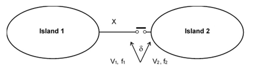
Figure 5 - An illustration of fully separated islands
The islands are considered fully separated if there is no connection between them and both islands have a sustainable generation-load balance. The islands from a synchronization perspective are rotating with their own frequency f1 and f2 which ideally should be the same and equal to 50Hz. This however is not achievable in practice and the two frequencies always differ with a slip frequency df = f2 – f1. Transmission lines and bus couplers are usually equipped with synchro-check or synchronizing facilities. Transmission transformers are usually not equipped with synchronizing facilities but in cases where they are, they can also be used for islands synchronization. Connecting separated islands without any synchronism check facilities is absolutely prohibited as it may result in damage to generators’ shafts due to excessive torsional stress.
Synchronization settings on synchronizing equipment are normally calculated or standardized for system normal running conditions to enable full utilization of transmission assets and good system flexibility while maintaining generators stress at acceptable level. The synchronizing equipment are not developed to provide for appropriate synchronization of fully separated islands. This situation is further worsened by the network composition during restoration for example fewer generators available. Transmission networks are also equipped with many different technologies of synchronization facilities applied over the years with significant differences in their measurements, operation and accuracies. Most modern relays are equipped with not only synchro-check functionality but also with full synchronization functionality that allows for very precise synchronization of asynchronous islands with calculated or predicted angle very close to zero. Wherever possible, lines or bus couplers with such synchronization facilities should have a priority in driving the process of island re-synchronization.
Synchronization angles on the generator terminals must be kept within strict OEM limits of usually 5–6 deg. Synchronization at locations far away from the generator should take into account the impedance between the generator and synchronization location. This impedance provides significant cushion to torsional stresses and much larger angle settings are possible.
Key learnings
The key learnings or take-away for the members of this working group members (from 11 CIGRE countries and 22 contributors) are:
- Need of accurate and detailed modelling of network components for restoration studies.
- Type of simulation and choice of simulation tool is to be taken into account during blackstart/re-energization planning studies.
- Need of mock drills in investigating protection issues with regards to restoration process.
- Need for analysis of the different protection functions and special protection schemes during blackstart/re-energization.
- Importance of the use of communication i.e. Phasor Measurement Units (PMUs) in the blackstart/re-energization and resynchronization process.
Future work
Protection and automation issues that have been discussed are with regards to traditional and current restoration strategies. The power system is moving towards a low carbon network with high penetration of non-conventional forms of generation such as wind power plants, solar power plants and energy storage elements. HVDC transmission schemes are also undergoing continuous development with more DC transmission schemes envisaged in the future. There have been limited practical cases with regards to participation of the above technologies in the initial stages of network restoration either due to limited know how and intermittency of most of the non-hydro renewable sources. At the same time the power system is evolving, there is an increase in the number of disasters occurring creating resilience (rather than reliability) based scenarios thus different types of generation systems should be investigated with the aim of enhancing their blackstart capabilities and actively participating during restoration.

Other Technical Brochures