Update of service experience of HV underground and submarine cable systems
The electric utility industry relies on accurate data to make informed decisions about underground and submarine, high-voltage cable installations. This includes decisions on method of installation, type of cable insulation, and type of accessories.
To support these decisions, CIGRE has been gathering statistics from cable systems in service since at least 1977.
Convenor
(DK)
S. DAMSGAARD MIKKELSEN
Secretary
(DK)
J. FABRICIUS NIELSEN
K. IWASAKI (JP), A. PELIZZONI (IT), J. MOENS (BE), R. MOSIER (US), A. DÍEZ OSORIO (ES), H. STAGGE (DE), S. BIYELA (SA), R. ROSSETTI (FR), H. YOUNES (CA)
Corresponding Member: J. LANSLEY (AU)
In 2009, the results of the latest survey were published in TB 379 covering land cable systems for the years 2001 to 2005 and submarine cable systems for the years 1991 to 2005.
Since then, significant quantities of cables and accessories have been installed and the associated technology and laying techniques have matured and evolved. In particular, the quantity of submarine cables has grown, mainly as a consequence of offshore wind power installations and interconnectors.
This Electra article provides a high-level summary outcome for the Technical Brochure developed by CIGRE Working Group B1.57.
Scope
The Technical Brochure is an update of the service experience gained from the 10-year period of 2006 to 2015 with regard to underground and submarine AC and DC cable systems operating at or above 60 kV.
The information gathered and published includes the following:
- Land and submarine cables and accessories
- Current type (AC or DC)
- Cable type
- Installation mode
- Internal and external faults
The following cable types are considered:
- SCOF - Self-Contained Oil-Filled cables
- MIND - Mass-Impregnated Non-Draining cables
- HPOF - High-Pressure Oil-Filled
- GC – Gas-Insulated Cables
- EPR - Extruded Ethylene Propylene Rubber
- PE - Extruded Low Density Thermoplastic Polyethylene
- XLPE - Extruded Cross-Linked Polyethylene
Population of land cables
The table below shows the quantities of cables reported in recent surveys compared to this WG B1.57 land cable survey and older WG B1.10 survey results published in 2009 (CIGRE TB 379).
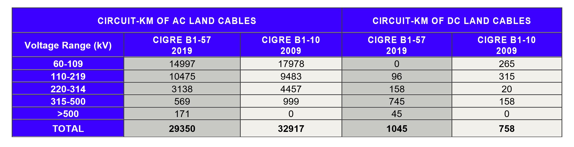
A total of 29,350 circuit-km of AC land cable was reported for this survey. In the voltage range 60 to 219 kV for AC land cables:
- 75% are XLPE
- 20% are SCOF
- 2% are HPOF
- 3% are others
For AC land cables 220 kV and above:
- 60% are XLPE
- 29% are SCOF
- 10% are HPOF
- 1% are other cable types
Since the year 2005:
- 24% of the recorded AC land cables from the survey were installed from 2006 to 2015
- Almost all installed AC land cables have been XLPE cables (98%)
- SCOF and HPOF cables only account for 0.7% and 0.5% respectively. EPR-insulated cables account for 0.7%
- No PE cables have been installed since 2005
A total of 1,045 circuit-km of DC land cable was reported for the survey. Of the DC land cables reported, extruded-dielectric cables account for 64%, SCOF cables account for 19%, and MIND cables account for 17%. Furthermore; 72% of all reported DC land cables have been installed since 2005.
Reported Faults on land cable systems
A total of 744 faults were reported on land cable systems for the 2006-2015 period. Only 2 faults were reported on DC land cables and the remaining 742 faults were on AC land cables.
For land cables, internal failures account for 64% of all failures versus 29% for external failures. The remaining 7% of the faults have unknown cause.
While it is commonly believed that accessories are more likely to fail than the cable itself, it was noted that 56% of all faults were attributed to the cable, 16% to joints, 18% to terminations, and 9% to other components.
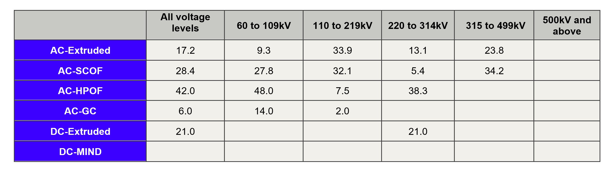
The following table presents the failure rate (internal and external) of AC land cables (excluding accessories) by voltage and insulation type.
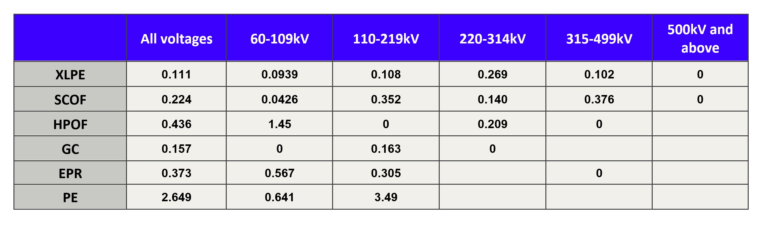
AC Land Cable Failure Rate (faults per 100-km-yr)
The following observations are made:
- The cable failure rate for SCOF cable systems is approximately twice the failure rate of XLPE cable systems. Note, however, that the average age of SCOF cable systems is significantly greater than XLPE cable systems;
- HPOF and EPR cable systems have cable failure rates that are in the range of four times the failure rate of XLPE cable systems;
- PE cable systems have a very high cable failure rate – more than 20 times the cable failure rate of XLPE cable systems. However, note that the population of PE cables in the survey is very low (< 0.5%);
- The cable failure rate has increased around 30% for XLPE cables since TB 379 was published. Behind this increase is covered a very large increase in the internal failure rates (app. 130%) and a significant decrease (app. 40%) in the external failure rate;
- The cable failure rate has increased around 50% for SCOF cables since TB 379 was published. This is due to a very large increase in the internal failure rates (app. 120%) and a slight increase (app. 20%) in the external failure rate.
The following tables present the failure rates of AC land cable accessories by voltage level.
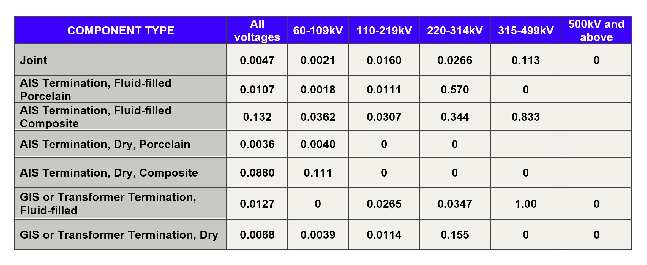
Extruded AC land cable accessories failure rate (faults per 100-unit-yr)
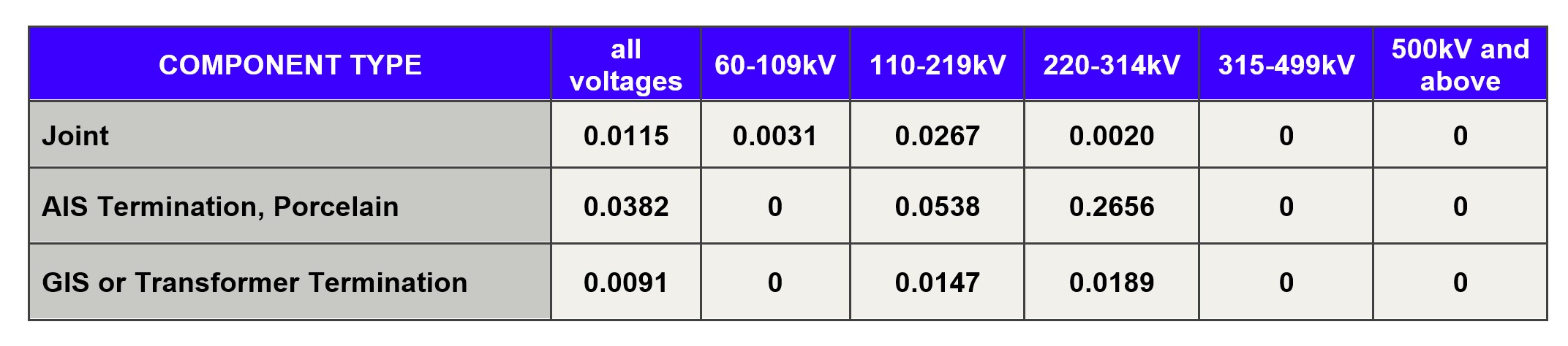
SCOF AC Land Cable Accessories Failure Rate (faults per 100-unit-yr)
The following can be observed from these two tables:
- The failure rate of joints on SCOF cable systems is 2.4 times higher than on extruded cable systems
- For extruded cable systems, there is a tendency towards an increasing joint failure rate at higher voltages, whereas the tendency is the reverse for SCOF cable systems. This may be influenced by the smaller populations as the voltage increases.
- On extruded cables, AIS fluid-filled terminations with composite insulators have a much higher failure rate than other types of terminations. The failure rate is more than 12 times as high as AIS fluid-filled terminations with porcelain insulators
- Dry-type AIS terminations with composite insulators on extruded cables for voltages less than 110 kV have a much higher failure rate (more than 60 times) than conventional fluid-filled terminations with porcelain insulators
- For GIS or transformer terminations on extruded cables, the failure rate is almost double for fluid-filled terminations than for dry-type terminations
- The XLPE joint failure rate has decreased 40% since TB 379 was published, and the XLPE termination failure rate has increased 300% compared to TB 379
- The SCOF joint failure rate has increased 90% since TB 379 was published, and the SCOF termination failure rate has increased 170% compared to TB 379
Outage times for land cable systems
The following table shows the average outage time for faults on the different cable systems depending on voltage level.
Outage times for land cables (days)
The average outage times for XLPE and SCOF cables are in the same range as they were in 2009.
Submarine cable systems
1,530 km of AC submarine cables and 4,567 km of DC submarine cables were reported in the questionnaires. 65% of all reported AC submarine cables were installed from 2005 to 2016, whereas 72% of DC submarine cables were installed during the same period.
69% of AC submarine cables are XLPE insulated, and 23% of AC submarine cables are SCOF insulated. Regarding DC submarine cables, those with extruded insulation account for 17%, MIND cables account for 67%, and SCOF cables account for 16%.
The Technical Brochure goes into greater detail on the failure rates and outage times for submarine cables, including information about the installation types.
It is interesting to note the following comparison:
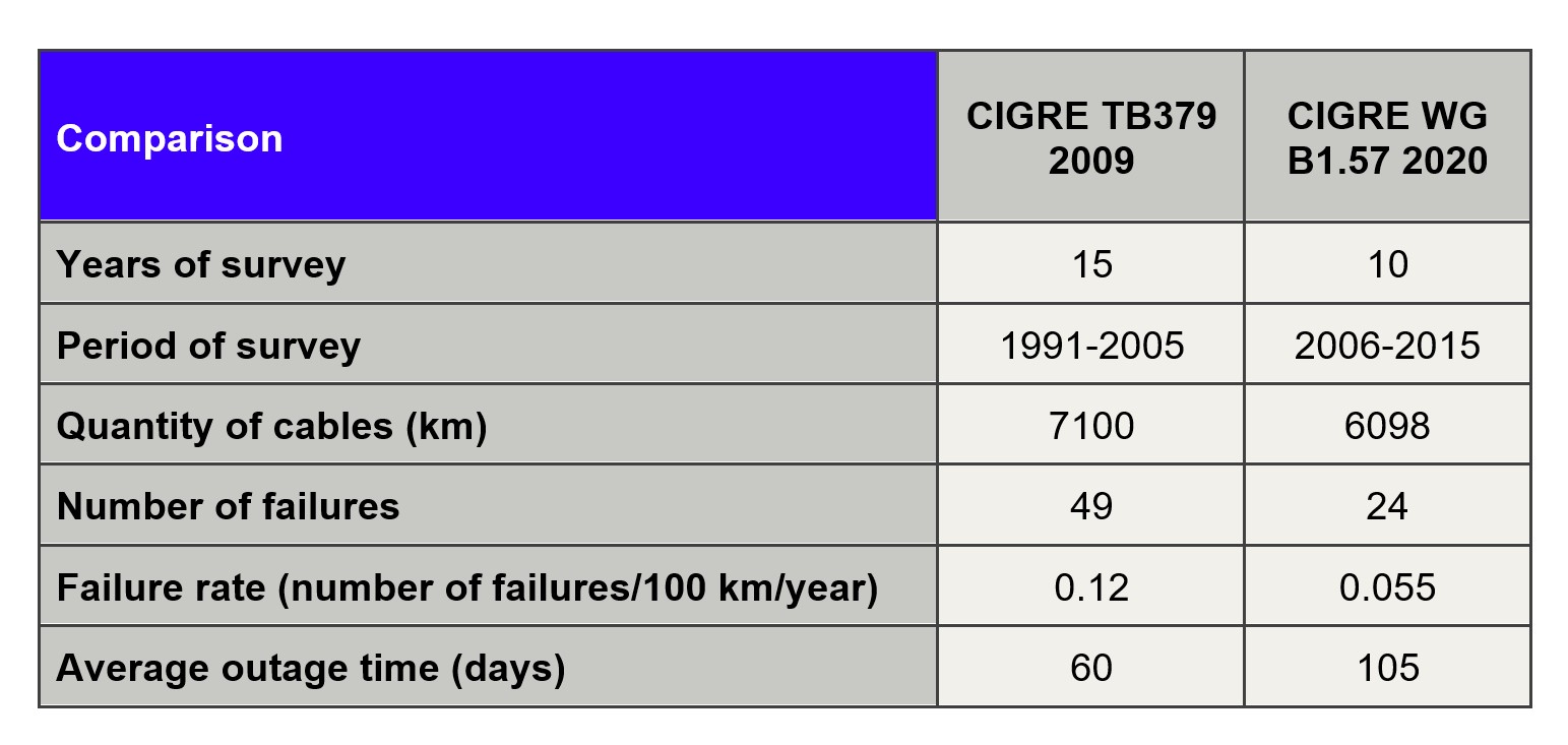
From this table, it can be observed that the failure rate for submarine cables is significantly lower than the failure rate from the previous survey. The main reasons for reduced failure rate are assumed to be:
- Improved methods for surveying and finding optimal cable routing,
- Improved methods for cable laying and protection, and
- Increased focus on protection by burial or other protection methods at installation.
It can also be observed that average outage times have increased significantly since TB 379 was published, increasing from approximately 2 months to 3.5 months. The reason for this increase can be reduced emergency repair preparedness at many utilities, but also due to many submarine cables in recent years being installed in areas with challenging weather conditions – like the North Sea.
Conclusions
Ten years have passed since the Technical Brochure 379 was published, and during that time a large number of renewable power stations have been built, requiring a large quantity of cable to link these power sources and to connect power systems internationally to utilize these resources. From the viewpoint of the stable use of these renewable resources and maintaining the power system reliability, it has been increasingly important to ensure the quality and reliability of the cable system.
Over the course of ten years, the trend of cable technology has changed. In the field of AC land cables, paper-insulated oil-filled cables have largely been replaced with XLPE cables. Although the ratio of MIND cable is still high for DC submarine cables, the application of XLPE cable has been extended at higher voltage levels thanks to recent technological developments.
The main objective of WG B1.57 was to collect reliable service and performance data on different types of cables, accessories, and installation methods. As all the information being generated is useful to the industry as a whole, it highlights the need for all utilities to have reliable processes to collect data on the installed cable system and faults that occur in service.

Other Technical Brochures