Dielectric testing of HVDC gas-insulated systems fundamentals for a future standard
Rapid, worldwide implementation of electrical power generation from renewable sources, often located at great distances from urban and industrial consumers, has led to the need for new, low loss, long-distance transmission systems. A result of this trend is that development of DC transmission technologies is progressing rapidly. As a part of this, gas-insulated DC transmission lines (DC GIL) and gas-insulated DC substations stations (DC GIS) are of particular interest due to their space-saving advantages.

Convenor of JWG D1/B3.57
Testing of these systems poses unique challenges and forms the basis for a reliable service performance. The technical feasibility and initial application of gas-insulated HVDC GIS was described in CIGRE Technical Brochure 506. Since its publication (2012), a large body of service experience had been collected from the first DC GIS installations, and further projects are expected to be realized soon. All these DC GIS were subjected to thorough dielectric testing, covering the basic phenomena but using different testing procedures and test levels, since no standards for (dielectric) testing of HVDC gas-insulated systems – the basis for a satisfactory reliability – are currently in place. Therefore, CIGRE Joint Working Group JWG D1/B3.57 was created which considered the following items in detail:
- Voltage and overvoltage stresses subjected to gas-insulated systems
- Basic phenomena and insulation properties at DC and overvoltage stresses
- Dielectric testing of gas-insulated HVDC systems to cover DC phenomena and to withstand dielectric stresses
- Recommendations for testing of gas-insulated HVDC systems (type tests, routine tests, on-site tests)
- Prototype installation test as long-term test; test arrangement and testing procedure, test equipment
The content of this newly Technical Brochure (to be published in 2020) will be described in the following. In the chapter dealing with voltage and overvoltage stresses of gas-insulated HVDC systems overvoltages originating either on the DC transmission line or at the converter are discussed, based on typical DC link designs and taking into account different converter technologies. For this, slow-front overvoltages (SFO) caused by earth faults at different fault locations on an example line of 400 km length are considered. The effects of such SFO stresses occurring at the converter terminal or DC substation are studied, along with the case of a GIL-OHL interface, e.g. when hybrid lines contain GIL sections. The effects of SFO occurring at converter terminals, caused by earth faults at either the DC side or AC side are also looked at. For the purpose of insulation coordination, SFO amplitudes of about 2 p.u. can be assumed. Regarding fast-front overvoltages (FFO), investigations of the stresses due to lightning in the vicinity of the converter terminals and a GIL-OHL interface are carried out. The FFO magnitudes amount to about 2.1 p.u., assuming adequate arrester ratings have been applied.
Subsequently, the basic phenomena and insulation properties under DC voltage and overvoltage stresses will be considered. First, conduction through solid insulation and along insulator surfaces, charge accumulation, field transition and effects at gas-solid insulation interfaces are described (Figure 1). After that, the insulating properties of gas-solid insulation systems are considered, starting with the insulation characteristics of the gas gap and the insulators under DC stress and overvoltage stresses, and followed by the presentation of the typical properties of insulating materials regarding volume and surface resistivity. Further influencing factors as electric field and temperature dependence, moisture, space charge etc. are examined and typical conductivity values are given. The final subchapter presents computational simulation and its verification. Most of the simulation tools are based on Finite Element Methods (FEM). In multi-physics simulation tools, the simulation of the electric field and charge distribution can be linked with the temperature distribution and the temperature - and field dependent material properties. The verification of the simulation is done by surface potential measurements on model insulators and on real insulators applied in gas-insulated systems.
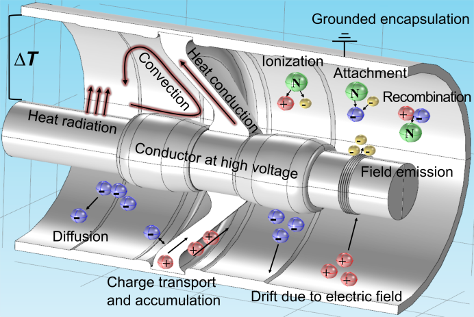
Figure 1 - Physical mechanisms in DC gas-solid insulation systems
Typical defects and their partial discharge (PD) characteristics will be considered in the next chapter. Defects in gas-insulated DC systems are similar to those found in AC systems: Mobile particles, protrusions on the HV conductor, particles lying on a spacer, displaced, misaligned or loose shields and voids in solid insulation components. As the most common defect in gas-insulated systems is caused by mobile particles and these are more harmful under DC stress, the consideration is focused on particle motion and the pulse sequence at positive and negative polarity. Particle bouncing and firefly phenomena are described in particular.
The following chapter addresses the background of dielectric testing for proving the capability to withstand the phenomena in gas-insulated DC systems described before. In the first subchapter the insulator in the gas-insulated environment and the basic idea of the electrical insulation system test, i.e. the testing philosophy, the testing procedure and examples for test-setups are explained (Figure 2). The second subchapter covers the particles including mitigation measures along with detection and identification of particles by PD testing and analysis of PD data. Methods of pulse sequence analysis (PSA) are described as a suitable tool for visualisation and identification of PD defects under DC voltage. The third subchapter deals with the performance of the insulating components over their lifetime. The consideration supports the conclusion of an uncritical ageing performance at DC voltage compared to AC voltage at the same dielectric stress. The fourth subchapter describes the prototype installation test which is carried out to collect more information about the long-term performance of this type of technology. A basic test scenario including test voltage levels and procedures for superimposed impulse voltage testing is presented.
The chapter “recommendations for dielectric testing of gas-insulated HV DC systems” provides the fundamentals for a future IEC Standard. It comprises type testing, routine testing and onsite testing, as well as the prototype installation test. The chapter defines test voltages, test currents and test levels, the test procedure, in particular the insulation system as an important part of the type test, and the acceptance criteria. For testing with superimposed voltages, no flashover across the insulator surface is permitted. It is recommended to perform initial PD testing under AC voltage in order to profit from the large body of AC PD experience accumulated till now, in contrast to the quite limited experience available with PD testing at DC voltage. For the prototype installation test the basic test sequence and different options are presented as well as the acceptance criteria, re-testing procedure (in the case defects are found or a flashover occurs), and a procedure in the case of interruptions.
The chapter “test equipment and test procedures” will provide guidance for users at dielectric testing of gas-insulated DC systems. Subchapter 1 deals with superimposed voltage testing. General explanations for the test circuit for composite voltages are given, the options for the generation of superimposed voltages, and the description of the coupling and blocking elements are presented (see also Figure 2). Examples of typical phenomena which can occur with different test setup options are given, and measures are described to avoid their negative impact on the test object. Sub-chapter 2 details the prototype installation test, the basic test circuit, the circuits to generate and inject high current at high voltage potential, the long-term test sequence and the superimposed voltage tests. Regarding the long-term test sequence, a procedure in case of test interruptions is specified. For test objects of long physical length test objects e.g. DC GIL, oscillating lightning and switching impulse testing is recommended due to the higher capacitance and inductance of the load.
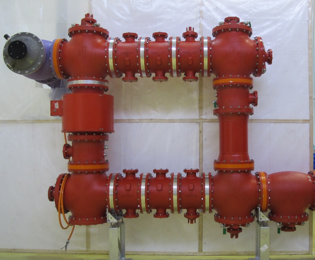
Figure 2a - DC insulation system test: Device under test with solid insulators
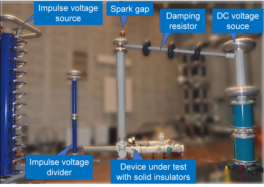
Figure 2b - DC insulation system test: test set-up, prepared for both DC and superimposed tests
Testing of the interface between DC cables and gas-insulated DC systems is the last chapter addressed. Those interfaces will appear more and more often, as gas-insulated DC systems are connected directly to DC cables, in order to utilize the space saving features of such arrangements. However, the testing philosophy for cables and gas-insulated systems and the test objectives are different. Taking into account these differences, a proposal for dielectric testing of these critical interfaces is made covering both test objectives. Finally, recommendations for the proceeding further in this subject are given. They can be used as the basis for further discussions in the relevant CIGRE Working Group recently created to deal with this subject, JWG B1/B3/D1.79, “Recommendations for dielectric testing of HVDC gas insulated system cable sealing ends”.
Suggested content