DC side harmonics and filtering in HVDC transmission systems
Technical Brochure is intended as a comprehensive guide to all aspects of DC side harmonics and filtering for HVDC systems. It will replace the only previous CIGRE Technical Brochure on the topic, TB 092, published in 1994, of which this Brochure is formally a revision.
Convenor
(UK)
N. SHORE
Secretary
(UK)
G. O’HEIDHIN
R. ATMURI (CA), B. BISEWSKI (CA), F. CATTAN (BR), J. COADY (CA), A. GANGADHARAN (IN), K. KENT (CA), K.L. KOO (UK), M. LIMA (BR), T. MAGG (ZA), T. MANNA (US), N. RAMAITE (XA), M. REYNOLDS (US), K. WALKER (CA), M. WEILAND (DE)
Corresponding members: S. HAMMER (DE), R. JUHLIN (SE), M. KANDIC (CA), C. KARLSSON (SE), M. LINARES (CA), P. RIEDEL (DE), K. ROGGENKAMP (DE), E. STARSCHICH (DE)
The main purpose of DC side filtering in HVDC systems is to prevent induced interference with nearby communication systems, especially metallic analogue telephone lines and railway signalling systems. While the conversion of many such telephone lines to digital or optical fibre technologies, and the use of mobile phones, has greatly decreased the possibility of such interference; nevertheless there remain large numbers of potentially vulnerable analogue telephone lines in service.
In practice, there have been few problems of harmonic disturbance from the DC side of the very many HVDC transmissions in service, and few problems relating to DC filter equipment in operation. This past experience indicates that designs in general have been at least adequate in terms of harmonic performance, and robust in terms of rating and equipment design. However, it is not obvious to what extent this satisfactory experience might indicate that DC filters in some instances may have been over-designed, and that a more economical approach might have been possible.
The voltage sourced HVDC converters (VSC), which have come to dominate the market, emit considerably lower magnitudes of DC side harmonics than the traditional line commutated converters (LCC). In addition, most VSC transmission schemes to date have used shielded underground cables, which reduces the range of any external interference. However, if such cables are laid in, or near to, roads, they may lie very close to existing telephone cables and, in such cases, interference remains a real risk.
Despite such reductions in potential interference, the topic of this Technical Brochure is of continued importance and relevance. As new instances of DC side filtering becomes less common, expertise in the subject is at risk of being lost. This Brochure is intended partly as a comprehensive repository of such knowledge, for future reference. It also addresses some key emerging topics related to DC side harmonics, and concerning interaction with nearby AC lines.
Harmonic generation and inductive coupling theory
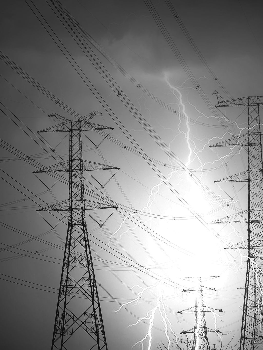
In the Brochure, the topic of harmonic generation and propagation is thoroughly described, for both line-commutated converters (LCC) and voltage-sourced converters (VSC). Issues concerning the flow of triplen-order harmonics through LCC converter transformer stray capacitances, and suitable modelling of the phenomenon, are extensively covered. The harmonic emissions of different types of voltage sourced converters are described, with discussion of the factors which most affect them. The most recent modular multilevel converters (MMC) typically produce extremely low levels of harmonics but over a very wide spectrum (Figure 1). The harmonic impedance of the converter as seen from the DC side is also considered, as this is an essential element in harmonic modelling of the HVDC system.
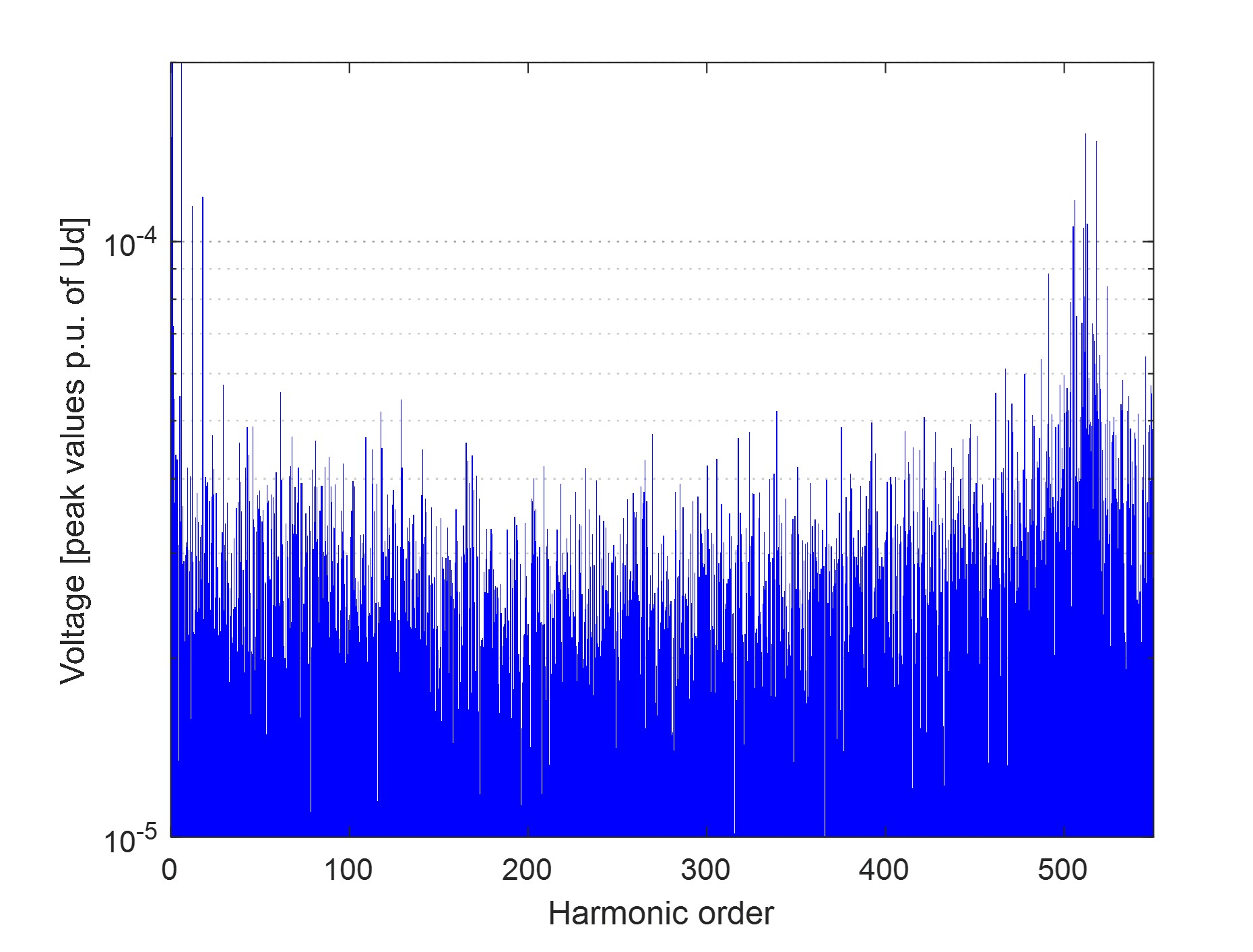
Figure 1 – Example of DC side harmonic spectrum of a MMC voltage sourced converter
Different modelling techniques for DC side harmonic studies are described along with advice on the representation of all relevant circuit components.
Key to the aspect of telephone interference, is the theory of inductive coupling to vulnerable communication systems. This is described in sufficient depth to facilitate a good understanding of the topic, with derivations of the mutual impedance between power and communication lines, and the frequency dependence of screening factors and the balance of telephone cable pairs. The Brochure condenses key aspects of published work in this area and provides equations and plots which will be of value to the practising engineer. The use of modal analysis is described, as this provides a clear way to envision the harmonic behaviour of the DC circuit and its external interactions.
Specification and verification of harmonic performance
The derivation and practical use of the induced voltage and the equivalent disturbing current criteria as metrics for specification and evaluation of harmonic performance are discussed, based on international standards for limitation of telephone noise, and advice is given as to practical ways to specify harmonic performance. A precondition for defining appropriate limits for the permitted DC side harmonic current is to assess the location and vulnerability of nearby telecommuniation lines. This may however be impracticable, especially if the HVDC line is thousands of kilometres in length and the Brochure discusses how to define harmonic performance limits even when information regarding possible victim telecommunication systems is sparse. Methodologies are suggested for rapid assessment of the risk of potential interference from a proposed new HVDC line or cable route (Figure 2 shows an example for an unscreened telephone cable – typically telephone cables would be screened and the disturbing current limits would be correspondingly higher).
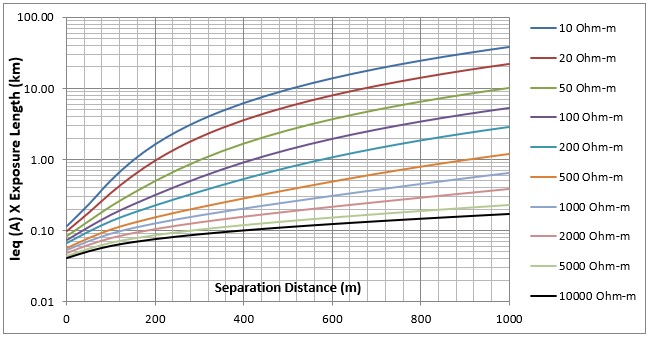
Figure 2 - Rapid assessment of maximum permissible equivalent disturbing current, as a function of earth resistivity and separation between power and an unscreened analogue telephone line governed by ITU-T noise limits
It is almost always necessary to make an assessment of the possible risk of interference from a new HVDC transmission, even if DC side filtering is eventually found not to be needed. The financial risks of possible shutdown or delayed commercial operation of the DC transmission due to excessive interference with third-party communication systems, or post-commissioning circuit modifications, can be extremely high and fully justify a detailed technical risk analysis during the design stage.
Compliance verification and site measurement is an area which is not well served by the literature, so this Brochure includes practical advice concerning different methods of measurement, with their respective advantages and disadvantages and a discussion of the limitations of accuracy. Direct measurement of harmonic currents in the DC conductors with sufficient accuracy of magnitude and phase may not be practicable, and instead measurements of the induced voltage in parallel test lines may provide a more direct assessment of the potential for inductive interference (Figure 3).
Figure 3 – Possible test line arrangement for measurement of inductive interference
DC filter design
Harmonic mitigation methods are described, including the use of DC filters and smoothing reactors, but also other aspects of converter design and measures on the telecommunication system side. An extensive chapter then deals with all aspects of the design of different types of DC side filters in terms of their performance and their component rating and specification (Figure 4). Transient rating, protection, economic aspects, reliability, audible noise, seismic design and several other relevant aspects of filter design are also discussed. The implications for filtering of neutral side smoothing reactors are analysed, and considerations for the paralleling of lines or DC filters of parallel HVDC transmissions are outlined. Practical example calculations of the effects of different aspects of circuit modelling and of DC filter design and location are given as illustrations.
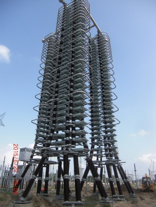
Figure 4 - 800 kV DC filter HV capacitor
The issue of possible DC circuit resonance must always be considered, as, if the DC circuit resonates at a critical frequency, then extreme levels of harmonic currents and voltages may be experienced, affecting component rating and the stability of control systems. The factors affecting pole mode and ground mode resonance of both overhead line and cable transmissions are discussed, including consideration of the active impedance of the HVDC converters, and steps that can be taken to avoid deleterious resonances are outlined.
Questions during refurbishment of HVDC projects
There are a great many existing LCC HVDC transmissions which will eventually require refurbishment. At such times it is often questioned whether their DC filters are still necessary – or can they be eliminated, or at least reduced, in order to avoid replacement of components, cut ongoing maintenance costs or reduce outage risks? The information provided in the Brochure should enable even non-specialist engineers to understand the justifications for, and design of, the existing filters and to judge what action may be viable. Various considerations other than telephone interference – such as resonance, control stability, harmonic stresses and suppression of overvoltages – may justify the retention of such existing DC filters, possibly with simplifying modifications.
Harmonic limitation in DC grids
DC grids have been much discussed in recent years, but the DC side harmonic aspects have received relatively little attention. In classical point-to-point HVDC transmissions the whole DC side system is an independent entity, normally belongs to one owner, and all relevant factors are known to the designer. In contrast, in a DC grid there may be a multiplicity of owners, and the grid may enlarge in stages such that its harmonic characteristics alter over time. Harmonic levels may increase as more connectees join the grid. The Brochure covers all such factors and draws parallels with the treatment of harmonics in an AC system, introducing the concepts of allowable harmonic limits, headroom, and allocation of limits to individual connections.
Fundamantal frequency coupling with AC lines
Due to the difficulty in obtaining permissions and land rights for new overhead line transmission, HVDC lines sometimes run in the same corridor as existing AC lines, or may even be located on the same transmission towers (Figure 5). In such cases, fundamental frequency currents may be induced in the HVDC circuit . As these flow through the HVDC converters they will be cross-modulated and may result in direct current flow in the converter transformers. This would tend to cause half-cycle saturation, high magnetizing currents and increased heating, harmonic generation and audible noise.
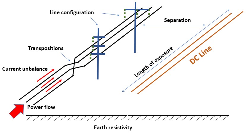
Figure 5 - Factors affecting fundamental frequency induction
This issue is predicted to have increasing relevance in future projects and will require to be analyzed in all such cases, even if mitigation is eventually determined to be unnecessary. Although the issue does not concern harmonics as such, the tools and methods for modelling and analysis are similar, and the mitigation methods are related, and so the inclusion of the topic is justified. The Brochure provides an analysis of all aspects of this phenomenon, including the important influence of the active control of the converter, for both LCC and VSC applications, and describes how fundamental-frequency blocking filters may be designed to mitigate the problem. The effectiveness of transpositions of the AC and/or the DC line is also analysed.
Conclusion
The Brochure provides guidance on all the issues regarding DC side harmonics which should be considered in the preparation of a Technical Specification for an HVDC project, and gives detailed practical advice on the specification of the individual items of filter equipment, with reference to applicable standards and tests.
A highly extensive reference section is included, which signposts all the important relevant publications in the field, facilitating access to deeper and more extensive treatments of each subject area covered in the Brochure.

Other Technical Brochures